Description
This 184 page, White 2-45 2-62 Diesel Field Boss Tractor Service Manual is a reproduction of the original, out of print manual. This tractor service manual provides detailed service and overhaul information, step-by-step repair instructions and maintenance specifications for White 2-45 2WD, 2-45 4WD, 2-62 2WD, 2-62 4WD, 2-62 4WD High Clearance tractors.
SERIAL NUMBER LOCATIONS – Tractor model and serial number plate is located on metal plate attached to left side on tractor frame. Tractor serial number is also stamped on left side of transmission case under operators platform. Engine serial number is stamped on left side of engine behind alternator.
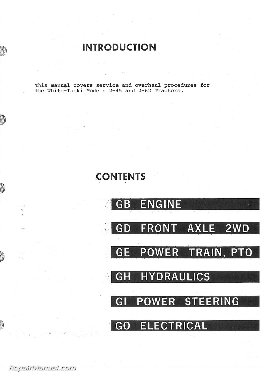
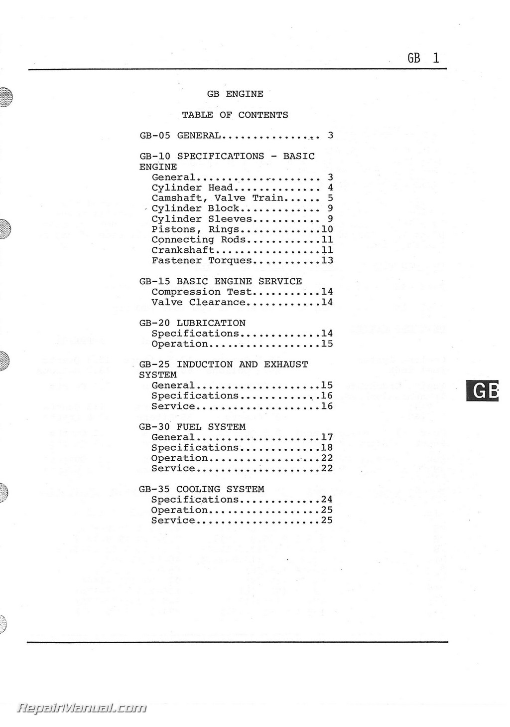
Table of Contents
Engine
GENERAL
SPECIFICATIONS – BASIC ENGINE
General
Cylinder Head
Camshaft, Valve Train
Cylinder Block
Cylinder Sleeves
Pistons, Rings
Connecting Rods
Crankshaft
Fastener Torques
BASIC ENGINE SERVICE
Compression Test
Valve Clearance
LUBRICATION
Specifications
Operation
INDUCTION AND EXHAUST SYSTEM
General
Specifications
Service
FUEL SYSTEM
General
Specifications
Operation
Service
COOLING SYSTEM
Specifications
Operation
Service
Front Axle 2WD
General
Operation
Specifications
Service
Axle – Exploded View
Pivot Pin Bushing
Knuckle Spindle Shaft
Front Wheel and Hub –
Exploded View
Front Wheel – Bearing
Adjustment
Power Train PTO
General
Reassembly of Tractor
Splitting Tractor
Specifications
Clutch
Transmission
Power Take-off
Differential/Pinion Shaft
Brakes/Final Drive/Axles
Four Wheel Drive
Torque Recommendations
Operation
Power Flow
PTO
Transmission
Differential/Final Drive
Four W/D Attachment
Gear Selection
Main Transmission
Range/Creeper
PTO
Clutch
Clutch Service
Adjustments
Free Play
Pedal Stop
Removal
Disassembly
Inspection
Assembly
Installation
Release Lever Adjustment
Release Bearing
Transmission
Exploded Views
Transmission
PTO
Front Transmission Case
Disassembly
PTO Clutch
Shift Cover
Range Gearbox
Shift Linkage
PTO Drive
Main Transmission
Assembly
Countergear
Reverse Gear
Top Shaft
PTO Drive Gears
Shift Rail and Fork
Range Gearbox
Shift Lever
PTO Clutch
Rear Transmission and Differential Case
Creeper Drive
PTO Rear Section
PTO Ground Speed
Differential
Exploded View
Drive Pinion
Assembly
Shim Adjustment
Differential Lock
Brakes/Final Drive/Axles
Brakes and Planetary Drive
Planetary
Actuator
Axle and Housing
Four Wheel Drive
Transfer Case
Propeller Shaft
Front Axle Bracket
Final Drive
Differential
Pinion
Hydraulics
General
Specifications
Operation
Service – Main System
Reservoir and Filter
Filter Location
Filter Components
Filter Service
Pump
Pump Exploded View
Components Locations
PTO Flow Divider
PTO Circuit
PTO Clutch Circuit
Cross-Section
Exploded View
Disassembly
Assembly
Adjustment
Hydraulic Housing
Junction Block
Remote Valve
Location
Circuit Diagram
Operation
Exploded View
Disassembly
Assembly
Main Control Valve
Three Point Hitch
General
Operation
Directional Control
Valve
Relief Valve
Compensator Valve
Holding Check Valve
Pilot Valve
Composite Function
Main Control Valve
Neutral Position
Lift Position
Lowering Position,
Disassembly
Assembly
Exploded View
Installation
Slow Return Check Valve with
Cylinder Safety Valve
General
Location
Cross-Sectional View
Circuit Schematic
Operation
Disassembly
Assembly
Cylinder
Location
Removal
Installation
Piston Seal Installation
Exploded View
Magnetic Strainer
Three-Point Hitch Linkage
General
Operation
Position Control Linkage:
Draft Control Linkage
Three-Point Hitch
Control Linkage –
Exploded View
Service
Linkage Adjustment
Position Control
Draft Control
Troubleshooting
Power Steering
General
Schematic – Power Steering System
Exploded View – Power Steering System
Specifications
Operation
Mechanical – Non Power Assist
Power Assist
Flow Control Valve
Relief Valve
Rotary Directional Valve
Service
Reservoir
Filter
Pump
Power Steering Unit
Removal
Disassembly
Inspection
Assembly
Adjustment
Flow Control Valve
Disassembly
Inspection
Assembly
Steering Urit Installation
Bleeding Procedure
Relief Valve Check and Adjustment
Troubleshooting
Electrical
Specifications
Battery
Alternator
Regulator
Starter
Lights
Fuses
Glow Plugs
Tractor Wiring Diagram
Alternator
Troubleshooting
Wiring Diagram
Disassembly
Reassembly
Inspection
Regulator
Diode Assembly
Rotor
Stater
Brushes
Starter
Operation
Troubleshooting
Disassembly
Inspection
Brushes
Armature
Field Coil
Overrunning Clutch
Solenoid Contacts
Magnetic Switch
Reassembly
Switches
Battery
Glow Plugs

 SKU: JS-OL-S-1355-1365
 SKU: WH-S-2-135-PLUS
 SKU: WH-O-2-63-15

