Description
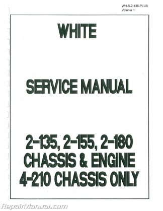
Do you need to service your White 2-135, 2-155, 2-180, or 4-210 tractor? This massive two volume White Tractor Service Manual is a reproduction of the original, out of print manual. This manual covers the engine and chassis for White 2-135, 2-155, and 2-180 tractors, however it covers only the chassis for 4-210 tractors.
This manual applies to the following tractors:
2-135 Diesel
2-135 Hydraulics & 3Pt only
2-155 Diesel
2-155 Hydraulics & 3 Pt only
2-180 Diesel
4-210 Diesel Chassis Only
Table of Contents
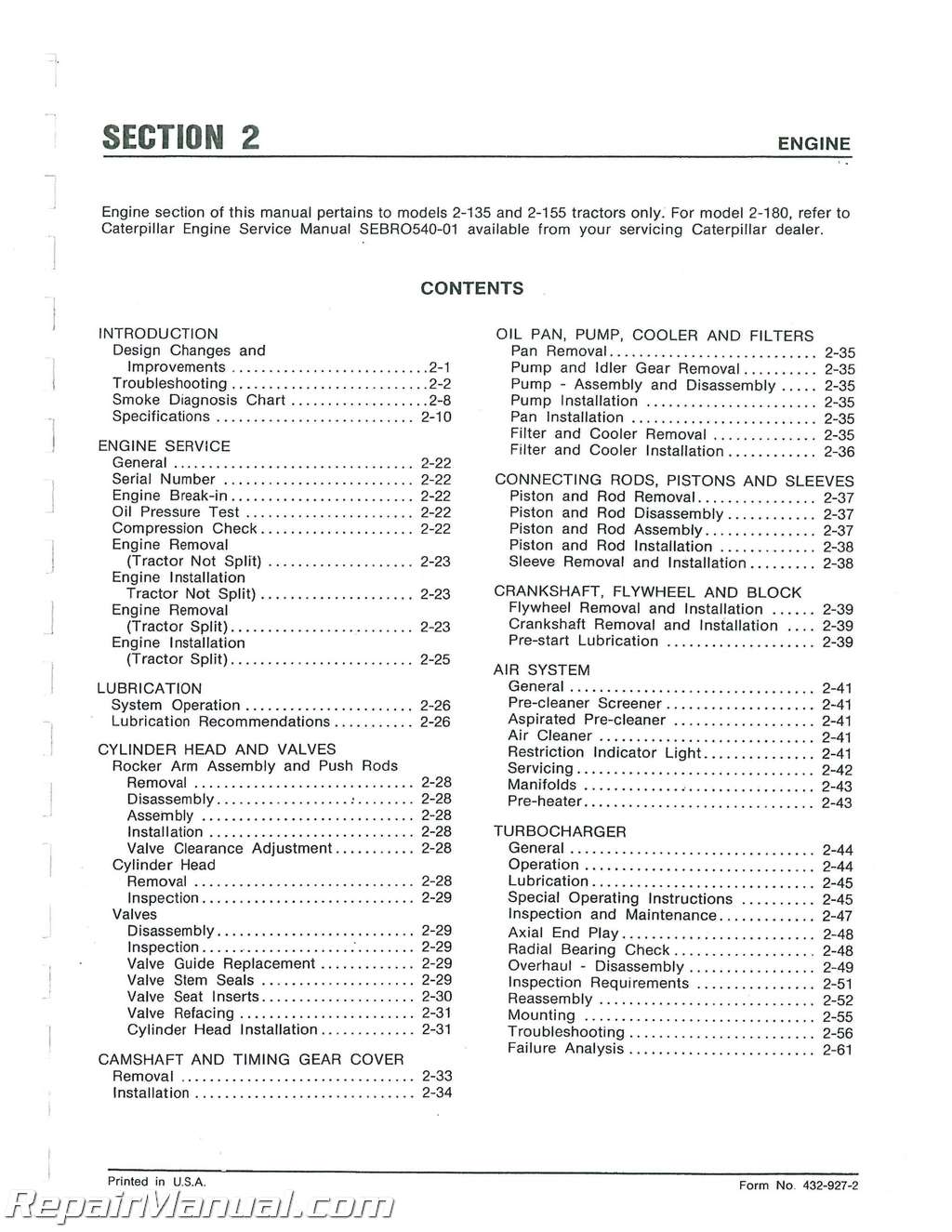
INTRODUCTION
SAFETY INSTRUCTIONS
MODELS 2-135 and 2-155 DIMENSIONS AND WEIGHTS
Dimensions
Weights
MODEL 2-180 DIMENSIONS AND WEIGHTS
Dimensions
Weights
TIRE SPECIFICATIONS
Front and Rear Tire 2-135/2-155
Front and Rear Tire 2-180
Power Front Axle Tire Recommendations
CAPACITIES
TORQUE CHARTS
Cap screws
Refrigerant Fittings
Steel Hydraulic Fittings
Pipe Plugs
Magnetic Drain Plugs
INTRODUCTION
Design Changes and
Improvements
Troubleshooting
Smoke Diagnosis Chart
Specifications
ENGINE SERVICE
General
Serial Number
Engine Break-in
Oil Pressure Test
Compression Check
Engine Removal
(Tractor Not Split)
Engine Installation
Tractor Not Split)
Engine Removal
(Tractor Split)
Engine Installation
(Tractor Split)
LUBRICATION
System Operation
Lubrication Recommendations
CYLINDER HEAD AND VALVES
Rocker Arm Assembly and Push Rods
Removal
Disassembly
Assembly
Installation
Valve Clearance Adjustment
Cylinder Head
Removal
Inspection
Valves
Disassembly
inspection
Valve Guide Replacement
Valve Stem Seals
Valve Seat Inserts
Valve Refacing
Cylinder Head Installation
CAMSHAFT AND TIMING GEAR COVER
Removal
Installation
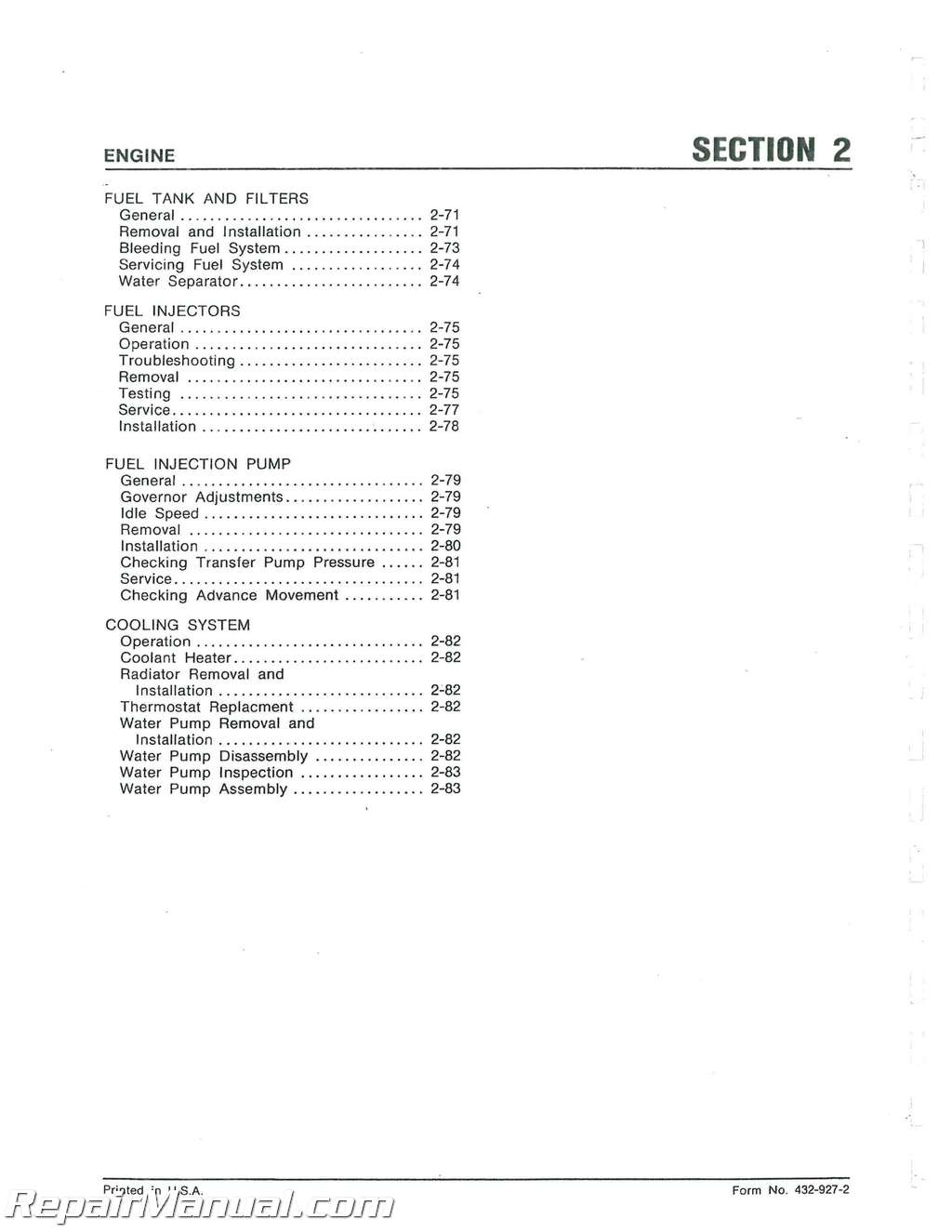
OIL PAN, PUMP COOLER AND FILTERS
Pan Removal
Pump and Idler Gear Removal
Pump – Assembly and Disassembly
Pump Installation
Pan Installation
Filter and Cooler Removal
Filter and Cooler Installation
CONNECTING RODS PISTONS AND SLEE
Piston and Rod Removal
Piston and Rod Disassembly
Piston and Rod Assembly
Piston and Rod Installation
Sleeve Removal and Installation
CRANKSHAFT FLYWHEEL AND BLOCK
Flywheel Removal and Installation
Crankshaft Removal and Installation
Pre-start Lubrication
AIR SYSTEM
General
Pre-cleaner Screener
Aspirated Pre-cleaner
Air Cleaner
Restriction Indicator Light
Servicing
Manifolds
Pre-heater
TURBOCHARGER
General
Operation
Lubrication
Special Operating Instructions
Inspection and Maintenance
Axial End Play
Radial Bearing Check
Overhaul – Disassembly
Inspection Requirements
Reassembly
Mounting
Troubleshooting
Failure Analysis
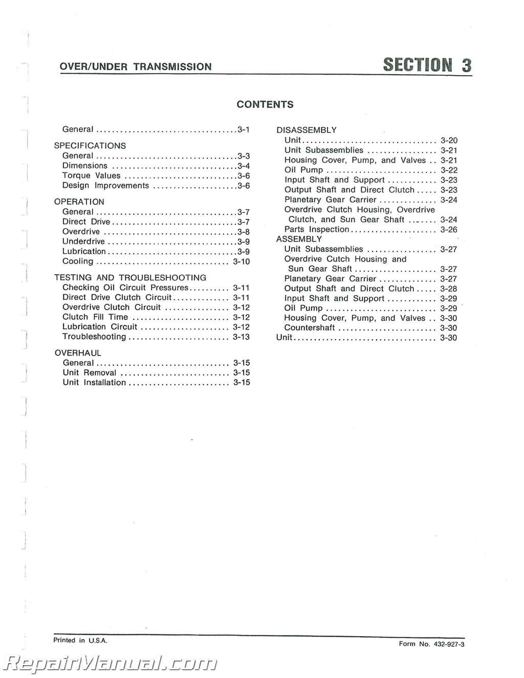
Transmission Over and Under
General
SPECIFICATIONS
General
Dimensions
Torque Values
Design Improvements
OPERATION
General
Direct Drive
Overdrive
Underdrive
Lubrication
Cooling
TESTING AND TROUBLESHOOTING
Checking Oil Circuit Pressures
Direct Drive Clutch Circuit
Overdrive Clutch Circuit
Clutch Fill Time
Lubrication Circuit
Troubleshooting
OVERHAUL
General
Unit Removal
Unit Installation
DISASSEMBLY
Unit
Unit Subassemblies
Housing Cover, Pump, and Valves
Oil Pump
Input Shaft and Support
Output Shaft and Direct Clutch
Planetary Gear Carrier
Overdrive Clutch Housing Overdrive
Clutch,and Sun Gear Shaft
Parts Inspection
ASSEMBLY
Unit Subassemblies
Overdrive Cutch Housing and
Sun Gear Shaft
Planetary Gear Carrier
Output Shaft and Direct Clutch
Input Shaft and Support
Oil Pump
Housing Cover Pump, and Valves
Countershaft
Unit
Drive Train
GENERAL
Design Changes and Improvements
Specifications
CLUTCH
General (2-135/2-155)
Safety Start Switch
Clutch Pressure Deactivator
Switch
Linkage Adjustment
Removal
Installation
PTO Drive Hub and Pilot Bearing
Disassembly
Assembly
Reconditioning Clutch Cover Assembly
General
Disassembly
Assembly
Release Lever Adjustment
General (2-180)
Operation
Linkage Adjustment
Removal
PTO Drive Hub and Pilot Bearing
Disassembly
Assembly
Clutch Repair
Disassembly
Adjustment
Assembly
Installation
TRANSMISSION
General
Operation
Lubrication System
Operation
Checking System
Hydraulic Pump
Removal
Installation
Drive Gear Removal
Drive Gear Installation
Transmission Disassembly
Preparation
Shifter Mechanisms
Input Shaft
Countershaft
Bevel Pinion Shaft
Reverse Idler Gear
Park Lock Latch and Rod
Transmission Assembly
Park Lock Latch and Rod
Reverse Idler Gear
Bevel Pinion Shaft
Countershaft
Input Shaft
Shifter Mechanism
BRAKES
General
Operation
Brake Disc Removal and Installation
Pressure Plate and Piston
Removal and Disassembly
Assembly and Installation
Bleed Screw
Brake Valve
Removal and Installation
Disassembly
Assembly
Brake Pedal Linkage
Adjustment
Bleeding
REAR AXLES CARRIERS AND PLANETARY
Axle Carrier and Planetary
Removal
Installation
Disassembly
Assembly
Differential
Lock Operation
Removal
Installation
Disassembly
Assembly
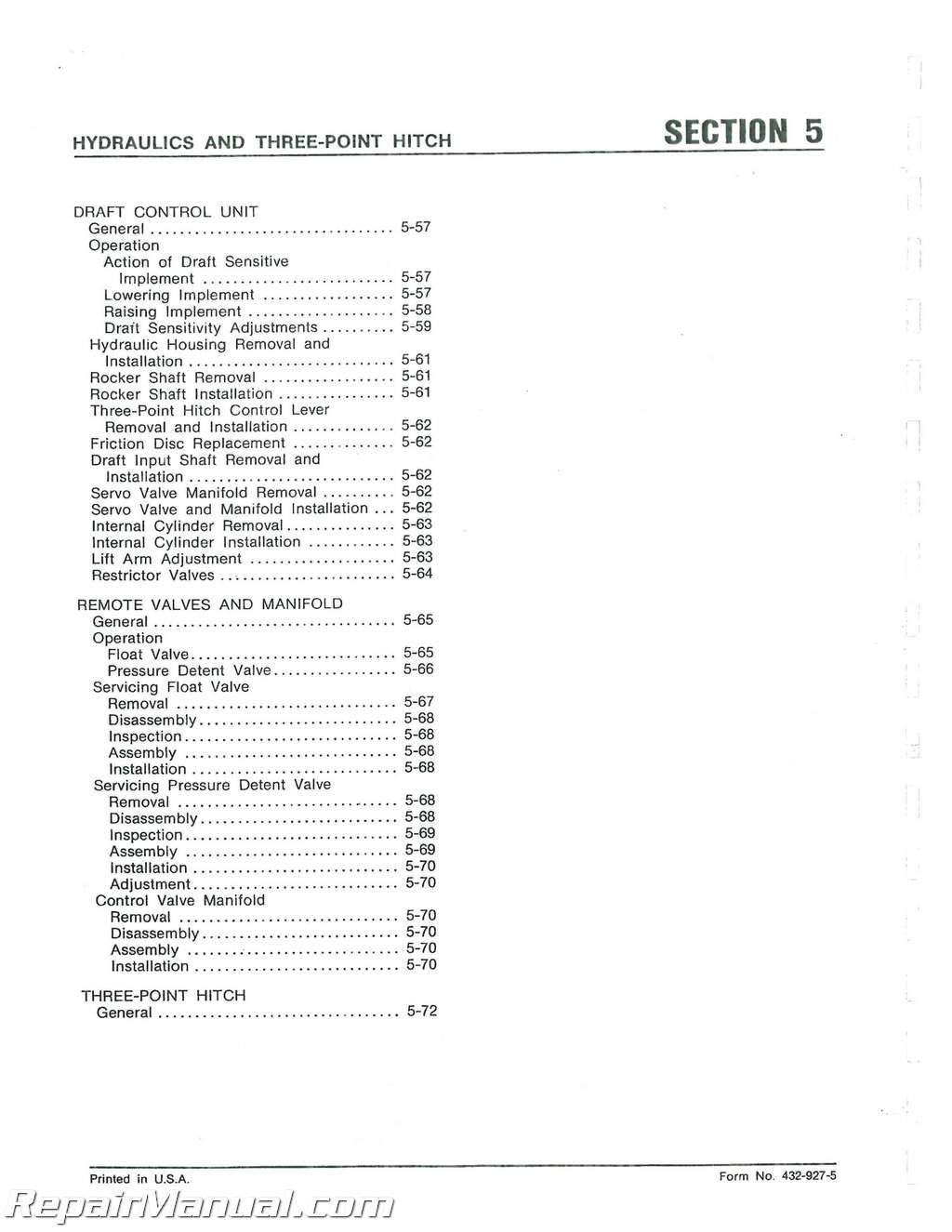
Hydraulics and Three Point Hitch
SPECIFICATIONS
General
Hydraulic Pump
Charge-lube Pump
Internal Cylinder (Hitch Cylinder)
Remote Control Valve-Pressure Detent
Pressure Control Valve
Torque Valves
Leakage Specifications
Design Changes and Improvements
GENERAL
TESTING AND TROUBLESHOOTING
General
Bleeding System
Testing
Charge-lube Pump Reservoir
Filter, and Cooler
Hydraulic Pump
Pressure Control Valve
Servo Valve
Steering Control Unit
Brake Valvo
Quick Check
Service Tools Required
Material Required
Troubleshooting Guide
Hydraulic Test Sequence
CHARGE-LUBE PUMP AND INLET SCREEN
Charge-lube Pump
General
Removal
Installation
Disassembly
Assembly
Inlet Screen
Removal
Installation
HYDRAULIC FILTER
General
Filter Head
Removal
Installation
Cooler Bypass Valve
Removal
Installation
Pressure Regulating Valve
Removal
Installation
HYDRAULIC PUMP
General
Operation
Overhaul
General
Disassembly
Inspection
Assembly
Checking, Adjusting Preload of
Yoke Bearings
Checking, Adjusting Drive Shaft
Bearing Preload
Final Assembly
PRESSURE CONTROL VALVE
General
Operation
Unloader Valve
High Pressure Relief Valve
Priority Valve
Pressure Reducing and Low Pressure
Relief Valve
Servicing
General
Removal and Installation
Adjustment
Disassembly and Assembly
Unloader Valve
High Pressure Relief Valve
Priority Valve
Pressure Reducing and Low Pressure
Relief Valve
SERVO VALVE
General
Operation
Removal
Installation
Overhaul
General
Disassembly
Assembly
DRAFT CONTROL HYDRAULIC CYLINDER
Cylinder Removal and Installation
Cylinder and Piston
Cylinder Safety Valve
Overhaul
Adjustment
DRAFT CONTROL ACTUATING ASSEMBLY
General
Removal and Installation
Cross Shaft Installation
Pivot Shaft
Removal
Installation
Draft Control Spring
Power Take-off
SPECIFICATIONS
GENERAL
OPERATION
Dual Speed Units
LUBRICATION
PTO CLUTCH OPERATING TEST
REMOVING PTO AND DIFFERENTIAL
LOCK VALVE
SHAFT REMOVAL AND INSTALLATION
DUAL SPEED UNITS
PTO ASSEMBLY
Removal
Installation
Single Speed
Disassembly
Assembly
Dual Speed
Disassembly
Assembly
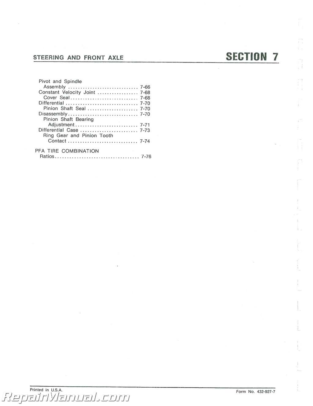
Steering and Front Axle
GENERAL
Design Changes and Improvements
Specifications
General
Special Torques
Troubleshooting And
Testing
Preliminary Checks
Steering System
Inspection
Troubleshooting Chart
STEERING CONTROL UNIT
Description
Operation
Neutral
Left and Right Turn
Manual Turning
Removal S/N 272-596 to 303-927
Installation S7N 272-595 to 300-927
Removal S/N 300-928 Up
Installation S/N 300-928 Up
General
Disassembly
Parts Inspection
Assembly
STEERING COLUMN
Description and Operation
Troubleshooting
Removal and installation
Disassembly
Early Model
Intermediate Model
Late Model
Parts Inspection
Assembly
Early Model
Intermediate Model
Late Model
2WD POWER STEERING CYLINDER –
Model 2-135/2-155
Removal
Installation
Disassembly
Parts Inspection
Assembly
2WD POWER STEERING CYLINDER –
Model 2-180
Removal and Disassembly
Inspection
Assembly
2WD FRONT END ASSEMBLY
Fronl Tire Toe-in Adjustment
Front Wheel Tread Width
Adjustment
Models 2-135/2-155
Removal
installation
Disassembly
Pitman Shall and Steering
Sector Arm
Steering Knuckle and Wheel
Hub
Parts Inspection
Assembly
Front Axle Carrier
Steering Knuckle and Wheel
Hub
Model 2-180
Removal and Disassembly
Assembly and Installation
PFA POWER STEERING CYLINDER
Description and Operation
Removal
Installation
Disassembly
Parts Inspection
Assembly
4PFA TRANSFER CASE
Description and Operation
Lubrication
Removal and Disassembly
Parts Inspection
Assembly and installation
PFA FRONT END ASSEMBLY
Axle, Carrier and Pivot
Replacement
Troubleshooting
Drive Shaft
Axle Differential
Axle Planetary
PFA DRIVE SHAFT
Removal and Disassembly
Parts Inspection
Assembly and Installation
PFA FRONT AXLE
Planetary Wheel End
Disassembly
Planetary Wheel End
Assembly
Pivot and Spindle
Disassembly
Electrical
GENERAL
Design Changes and Improvements
SPECIFICATIONS
Starling Motor
Alternator
2-135/2-155
2-180
Tractor Fuses and Circuit
Breakers
Lights
Sending Units
8atteries
Wiring Diagrams
BATTERIES
Safety Instructions
Troubleshooting
Battery Replacement
Battery Condition Check List
Electrolyte Level
Testing Specific Gravity of Electrolyte
Booster Battery or Charger Connections
Activating Dry Charged Batteries
Safety Guidelines
Battery Activation
BATTERY STORAGE
Off-Season Storage
Limited Use Storage
SWITCHES SENDERS AND WIRES
Light Switch
Key Switch
Engine OH Pressure Sender
Hydraulic Oil Temperature
Switch
Coolant Temperature Sender
Fuel Tank Sender
Transmission Lube Pressure
Switch
Air Reslrictor Indicator
Switch
Wring
Solenoids
Warning Lights
Gauges
Circuits
STARTING MOTOR
Description
Operation
Tests and Adjustments
No-Load Test
Interpreting Test Results —
Brush Holder Bench Check
Armature Bench Check
Field Winding Bench Check
Troubleshooting
Disassembly
Parts Inspection
Bushing
Assembly
General
Checking Gear Lash
Clearance
Final Testing
ALTERNATOR (2-135/2-156)
Description
Operation
Tests
Battery Installation Charging
and Testing Precautions
Preliminary inspection
Test Equipment and
Installation
Battery Voltage and Isolation
Diode
Excitation Circuit
Open isolation Diode
Voltage Regulator Setting
Field Currant Draw
Output and System Test
Bench Test
Disassembly
Parts Inspection and Testing
Housings
Isolation Diode
8rush Assembly
Rectifier Diodes
Stator Assembly
Rotor Assembly
Assembly
Installation
ALTERNATOR (2-180)
Description
Operation
Maintenance
Testing On Vehicle
Bench
Static
Disassembly
Assembly
TACHOURMETER
Cab
GENERAL
Design Changes and Improvements
SPECIFICATIONS
Air Conditioning System
General
Hoses
Condenser
Evaporator
Air Filters
Circuit Breakers
Expansion Valve
Receiver-Drier
Clutch
Controls
Compressor
Torque Valves
Refrigerant Fittings
Service Tools
Centigrade to Fahrenheit Chart
Temperature – Pressure Relation Chart
Fahrenheit
Centigrade
Cab Removal
Series I and II
Series III
Cab Installation
Series I and II
Series III
Cab Glass and Molding
Specifications
Seat Suspension
S/N 272 595 – 293 408
S/N 293 409 – Up
Heater
Windshield Wiper
Air Conditioning System
Description
R-12 Refrigerant
Compressor
Condenser
Receiver-Drier
Expansion Valve
Evaporator
Cab Controls
Operation
Safety Precautions
Tests and Adjustments
Preliminary Visual Check
Test Equipment
Accuracy of Manifold Gauges and Thermometer
Connecting Manifold Gauges
Checking Temperature – Pressure Relationship
Testing for Leaks
Leak Detectors
Discharging System
Flushing System
Purging System
Evacuating System
Evacuating Wet or Contaminated
System
Charging System
Tests and Adjustments – Individual Components Compressor
Expansion Valve
Receiver-Drier
Clutch Belt
Warning Light
Evaporator and Condenser Core
Repairs
Hose Replacement
Troubleshooting
Correcting Malfunctions
Air Compressor (Tecumseh or York)
Description
Service Valves
Tests and Adjustments
Changing Oil
Checking for Leaks
Noise Complaints
Removal
Installation
Disassembly
Magnetic Clutch
Cylinder Head and Valve Plate
Seal Assembly
Parts Inspection
Assembly
Seal Assembly
Clutch
Valve Plate and Cylinder Head
Air Compressor (Sankyo)
Description
Tests and Adjustments
Checking Oil Level
Troubleshooting
Removal
Installation
Disassembly
Clutch
Shaft Seals
Cylinder Head and Valve Plate
Parts Inspection
Assembly
Cylinder Head and Valve Plate
Clutch

