Description
This 2012 2013 2014 2015 2016 Suzuki DL650A Service Manual is the real deal printed publication from Suzuki. This manual provides detailed service information, step-by-step repair instruction and maintenance specifications.
Suzuki DL650A Service Manual Motorcycle Coverage
2012, 2013, 2014, 2015 2016 Suzuki DL650A
Table of Contents
Precautions
General Information
Maintenance and Lubrication
Service Data
Engine
Precautions
Engine General Information and Diagnosis
Emission Control Devices
Engine Electrical Devices
Engine Mechanical
Engine Lubrication System
Engine Cooling System
Fuel System
Ignition System
Starting System
Charging System
Exhaust System
Suspension
Precautions
Suspension General Diagnosis
Front Suspension
Rear Suspension
Wheels and Tires
Driveline I Axle
Precautions
Drive Chain / Drive Train / Drive Shaft
Brakes
Precautions
Brake Control System and Diagnosis
Front Brakes
Rear Brakes
ABS
Transmission / Transaxle
Precautions
Manual Transmission
Clutch
Steering
Precautions
Steering General Diagnosis
Steering / Handlebar
Body and Accessories
Precautions
Wiring Systems
Lighting Systems
Combination Meter / Fuel Meter / Horn
Exterior Parts
Body Structure
Suzuki DL650A Service Manual Index of Topics
Section 0 – General Information
General Description
Symbols
Abbreviations
SAE-to-Former SUZUKI Term
Vehicle Side View
Vehicle Identification Number
Fuel and Oil Recommendation
Engine Coolant Recommendation
BREAK-IN Procedures
Cylinder Identification
Country and Area Codes
Wire Color Symbols
Warning, Caution and Information Labels
Location
Component Location
Electrical Components Location
Specifications
Specifications
Special Tools and Equipment
Special Tool
Maintenance and Lubrication
Precautions
Precautions for Maintenance
General Description
Recommended Fluids and Lubricants
Scheduled Maintenance
Periodic Maintenance Schedule Chart
Lubrication Points
Repair Instructions
Air Cleaner Element Replacement
Air Cleaner Element Inspection and Cleaning
Exhaust Pipe Bolts and Muffler Bolts
Inspection
Valve Clearance Inspection and Adjustment
Spark Plug Replacement
Spark Plug Inspection and Cleaning
Fuel Line Inspection
Evaporative Emission Control System
Inspection (E-33 Only)
Engine Oil and Filter Replacement
Throttle Cable Play Inspection and
Adjustment
Throttle Valve Synchronization
Cooling System Inspection
Clutch System Inspection
Drive Chain Inspection and Adjustment
Drive Chain Cleaning and Lubricating
Brake System Inspection
Tire Inspection
Steering System Inspection
Front Fork Inspection
Rear Suspension Inspection
Chassis Bolt and Nut Inspection
Compression Pressure Check
Oil Pressure Check
SDS Check
Specifications
Tightening Torque Specifications
Special Tools and Equipment
Recommended Service Material
Special Tool
Service Data
Specifications
Service Data
Tightening Torque List
Section 1 – Engine
Precautions
Precautions
Precautions for Engine
Engine General Information and
Diagnosis
General Description
Injection Timing Description
Self-Diagnosis Function
Schematic and Routing Diagram
FI System Wiring Diagram
Terminal Alignment of ECM Coupler
Component Location
FI System Parts Location
Diagnostic Information and Procedures
Engine Symptom Diagnosis
Self-Diagnostic Procedures
Use of SDS Diagnosis Reset Procedures
Show Data When Trouble (Displaying Data at
the Time of DTC)
SDS Check
DTC Table
Fail-Safe Function Table
FI System Troubleshooting
Malfunction Code and Defective Condition
Table
DTC “C12” (P0335): CKP Sensor Circuit
Malfunction
DTC “C13” (P1750) or “C17” (P0105): IAP
Sensor Circuit Malfunction
DTC “C14” (P0120-H/L): TP Sensor Circuit
Malfunction
DTC “C15” (P0115-H/L): ECT Sensor Circuit
Malfunction
DTC “C21” (P0110-H/L): IAT Sensor Circuit
Malfunction
DTC “C23” (P1651-H/L): TO Sensor Circuit
Malfunction
DTC “C24″ (P0351) or “C25” (P0352): Ignition
System Malfunction
DTC “C28” (P1655): Secondary Throttle
Valve Actuator (STVA) Malfunction
DTC “C29” (P1654-H/L): Secondary Throttle Position Sensor (STPS) Circuit Malfunction
DTC “C31” (P0705): GP Switch Circuit
Malfunction
DTC “C32” (P0201), “C33” (P0202): Fuel
Injector Circuit Malfunction
DTC “C40” (P0505): ISC Valve Circuit
Malfunction
DTC “C41” (P0230): FP Relay Circuit
Malfunction
DTC “C42” (P1650): IG Switch Circuit
Malfunction
DTC “C44” (P0130 / P0135): H02 Sensor
(H02S) Circuit Malfunction
DTC “C60” (P0480): Cooling Fan Relay
Circuit Malfunction
DTC “C62” (P0443): EVAP System Purge Control Solenoid Valve Circuit Malfunction
(E-33 only)
DTC “C65” (P0506 / P0507): Idle Speed
Malfunction
Specifications
Service Data
Special Tools and Equipment
Special Tool
Emission Control Devices
Precautions
Precautions for Emission Control Devices
General Description
Fuel Injection System Description
Crankcase Emission Control System Description
Noise Emission Control System Description
Evaporative Emission Control System Diagram (Only for E-33)
Schematic and Routing Diagram
EVAP Canister Hose Routing Diagram (Only for E-33)
Repair Instructions
Heated Oxygen Sensor (H02S) Removal and Installation
Heated Oxygen Sensor (H02S) Inspection
Crankcase Breather (PCV) Hose Inspection
Crankcase Breather (PCV) Hose Removal and Installation
Evaporative Emission Control System
Removal and Installation (Only for E-33)
Evaporative Emission Control System
Inspection (Only for E-33)
Specifications
Service Data
Tightening Torque Specifications
Special Tools and Equipment
Special Tool
Engine Electrical Devices
Precautions
Precautions for Engine Electrical Device
Component Location
Engine Electrical Components Location
Diagnostic Information and Procedures
Engine Symptom Diagnosis
Repair Instructions
ECM Removal and Installation
CKP Sensor Inspection
CKP Sensor Removal and Installation
IAP Sensor Inspection
IAP Sensor Removal and Installation
TP Sensor Inspection
TP Sensor Removal and Installation
TP Sensor Adjustment
IAT Sensor Removal and Installation
I AT Sensor Inspection
ECT Sensor Removal and Installation
ECT Sensor Inspection
TO Sensor Removal and Installation
TO Sensor Inspection
STP Sensor Inspection
STP Sensor Adjustment
STP Sensor Removal and Installation
STV Actuator Inspection
STV Actuator Removal and Installation
ISC Valve Inspection
ISC Learned Value Reset and Opening
Initialization
H02 Sensor Inspection
H02 Sensor Removal and Installation
GP Switch Inspection
GP Switch Removal and Installation
Specifications
Service Data
Tightening Torque Specifications
Special Tools and Equipment
Recommended Service Material
Special Tool
Engine Mechanical
General Description
ISC Valve System Description
Schematic and Routing Diagram
Camshaft and Sprocket Assembly Diagram
Throttle Cable Routing Diagram
Diagnostic Information and Procedures
Engine Mechanical Symptom Diagnosis
Compression Pressure Check
Repair Instructions
Engine Components Removable with the
Engine in Place
Air Cleaner Element Removal and Installation Air Cleaner Element Inspection and Cleaning
Air Cleaner Box Removal and Installation
Throttle Body Components
Throttle Body Construction
Throttle Body Removal and Installation
Throttle Body Disassembly and Assembly
Throttle Body Inspection and Cleaning
Throttle Valve Synchronization
ISC Learned Value Reset
Engine Assembly Removal
Engine Assembly Installation
Engine Top Side Disassembly
Engine Top Side Reassembly
Valve Clearance Inspection and Adjustment
Camshaft Inspection
Cam Chain Tension Adjuster Inspection
Cam Chain Guide Inspection
Cam Chain Tensioner Inspection
Cylinder Head Disassembly and Assembly
Cylinder Head Related Parts Inspection
Valve Guide Replacement
Valve Seat Repair
Cylinder Inspection
Piston Ring Removal and Installation
Piston and Piston Ring Inspection
Engine Bottom Side Disassembly
Engine Bottom Side Reassembly
Conrod Removal and Installation
Conrod / Crankshaft Inspection
Conrod Crank Pin Bearing Inspection and
Selection
Crankshaft Journal Bearing Inspection and
Selection
Specifications
Service Data
Tightening Torque Specifications
Special Tools and Equipment
Recommended Service Material
Special Tool
Engine Lubrication System
Precautions
Precautions for Engine Oil
Schematic and Routing Diagram
Engine Lubrication System Chart Diagram
Engine Lubrication Circuit Diagram
Diagnostic Information and Procedures
Engine Lubrication Symptom Diagnosis
Oil Pressure Check
Repair Instructions
Engine Oil and Filter Replacement
Engine Oil Level Inspection
Oil Strainer / Oil Pressure Regulator Removal and Installation
Oil Strainer Inspection and Cleaning
Oil Pressure Regulator Inspection
Oil Cooler Removal and Installation
Oil Pressure Switch Removal and Installation
Oil Pressure Switch Inspection
Oil Jet Removal and Installation
Oil Jet / Oil Gallery Jet Inspection
Oil Pump Removal and Installation
Oil Pump Inspection
Oil Pipe Removal and Installation
Oil Pipe Inspection
Specifications
Service Data
Tightening Torque Specifications
Special Tools and Equipment
Recommended Service Material
Special Tool
Engine Cooling System
Precautions
Precautions for Engine Cooling System
Precautions for Engine Coolant
General Description
Engine Coolant Description
Schematic and Routing Diagram
Cooling Circuit Diagram
Water Hose Routing Diagram
Diagnostic Information and Procedures
Engine Cooling Symptom Diagnosis
Repair Instructions
Cooling Circuit Inspection
Radiator Cap Inspection
Radiator Inspection and Cleaning
Radiator / Cooling Fan Motor Removal and
Installation
Water Hose Inspection
Water Hose Removal and Installation
Radiator Reservoir Tank Inspection
Radiator Reservoir Tank Removal and
Installation
Cooling Fan Inspection
Cooling Fan Relay Inspection
ECT Sensor Removal and Installation
ECT Sensor Inspection
Engine Coolant Temperature Indicator
Inspection
Thermostat Removal and Installation
Thermostat Inspection
Water Pump Components
Water Pump Removal and Installation
Water Pump Disassembly and Assembly
Water Pump Related Parts Inspection
Specifications
Service Data
Tightening Torque Specifications
Special Tools and Equipment
Recommended Service Material
Special Tool
Fuel System
Precautions
Precautions for Fuel System
General Description
Fuel System Description
Diagnostic Information and Procedures
Fuel System Diagnosis
Repair Instructions
Fuel Pressure Inspection
Fuel Pump Inspection
Fuel Discharge Amount Inspection
Fuel Pump Relay Inspection
Fuel Hose Inspection
Fuel Hose Removal and Installation
Fuel Tank Removal and Installation
Fuel Pump Components
Fuel Pump Assembly Removal and
Installation
Fuel Level Gauge Inspection
Fuel Pump Disassembly and Assembly
Fuel Mesh Filter Inspection and Cleaning
Fuel Injector / Fuel Delivery Pipe Removal
and Installation
Fuel Injector Inspection and Cleaning
Specifications
Service Data
Tightening Torque Specifications
Special Tools and Equipment
Recommended Service Material
Special Tool
Ignition System
General Description
Immobilizer Description (For E-21, 24)
Schematic and Routing Diagram
Ignition System Diagram
Component Location
Ignition System Components Location
Diagnostic Information and Procedures
Ignition System Symptom Diagnosis
No Spark or Poor Spark
Repair Instructions
Ignition Coil Construction
Spark Plug Cap and Spark Plug Removal and
Installation
Ignition Coil Removal and Installation
Spark Plug Inspection and Cleaning
Ignition Coil and Plug Cap Inspection
CKP Sensor Inspection
CKP Sensor Removal and Installation
Engine Stop Switch Inspection
Immobilizer Antenna Removal and
Installation (for E-21, 24)
Ignition Switch Inspection
Ignition Switch Removal and Installation (for
E-21)
Ignition Switch Removal and Installation (for E-03, 24, 28, 33)
Specifications
Service Data
Tightening Torque Specifications
Special Tools and Equipment
Recommended Service Material
Special Tool
Starting System
Schematic and Routing Diagram
Starting System Diagram
Component Location
Starting System Components Location
Diagnostic Information and Procedures
Starting System Symptom Diagnosis
Starter Motor will not Run
Starter Motor Runs but Does not Crank the
Engine
Repair Instructions
Starter Motor Components
Starter Motor Removal and Installation
Starter Motor Disassembly and Assembly
Starter Motor Related Parts Inspection
Starter Relay Removal and Installation
Starter Relay Inspection
Turn Signal / Side-stand Relay Removal and
Installation
Side-stand / Ignition Interlock System Parts
Inspection
Starter Clutch Removal and Installation
Starter Clutch Inspection
Starter Button Inspection
Specifications
Service Data
Tightening Torque Specifications
Special Tools and Equipment
Recommended Service Material
Special Tool
Charging System
Schematic and Routing Diagram
Charging System Diagram
Component Location
Charging System Components Location
Diagnostic Information and Procedures
Charging System Symptom Diagnosis
Battery Runs Down Quickly
Repair Instructions
Battery Current Leakage Inspection
Regulated Voltage Inspection
Generator Inspection
Generator Removal and Installation
Regulator / Rectifier Construction
Regulator / Rectifier Inspection
Regulator / Rectifier Removal and Installation
Battery Components
Battery Charging
Battery Removal and Installation
Battery Visual Inspection
Specifications
Service Data
Tightening Torque Specifications
Special Tools and Equipment
Recommended Service Material
Special Tool
Exhaust System
Precautions
Precautions for Exhaust System
Diagnostic Information and Procedures
Engine Symptom Diagnosis
Repair Instructions
Exhaust System Construction
Exhaust Pipe / Muffler Removal and
Installation
Exhaust System Inspection
Specifications
Tightening Torque Specifications
Special Tools and Equipment
Recommended Service Material
Section 2 – Suspension
Precautions
Precautions
Precautions for Suspension
Suspension General Diagnosis
Diagnostic Information and Procedures
Suspension and Wheel Symptom Diagnosis
Front Suspension
Repair Instructions
Front Fork Components
Front Fork Removal and Installation
Front Fork Inspection
Front Fork Adjustment
Front Fork Disassembly and Assembly
Front Fork Parts Inspection
Specifications
Service Data
Tightening Torque Specifications
Special Tools and Equipment
Recommended Service Material
Special Tool
Rear Suspension
Repair Instructions
Rear Suspension Components
Rear Suspension Assembly Construction
Rear Shock Absorber Removal and
Installation
Rear Suspension Inspection
Rear Shock Absorber Inspection
Rear Suspension Adjustment
Rear Shock Absorber Disposal
Cushion Lever / Cushion Rod Removal and
Installation
Cushion Lever Inspection
Cushion Lever Bearing Removal and
Installation
Swingarm Removal and Installation
Swingarm Related Parts Inspection
Swingarm Bearing Removal and Installation
Specifications
Service Data
Tightening Torque Specifications
Special Tools and Equipment
Recommended Service Material
Special Tool
Wheels and Tires
Precautions
Precautions for Wheel and Tire
Repair Instructions
Front Wheel Components
Front Wheel Assembly Construction
Front Wheel Assembly Removal and
Installation
Front Wheel Related Parts Inspection
Front Wheel Dust Seal / Bearing Removal
and Installation
Rear Wheel Components
Rear Wheel Assembly Construction
Rear Wheel Assembly Removal and
Installation
Rear Wheel Related Parts Inspection
Rear Wheel Dust Seal / Bearing Removal and
Installation
Tire Removal and Installation
Wheel / Tire / Air Valve Inspection and
Cleaning
Air Valve Removal and Installation
Wheel Balance Check and Adjustment
Specifications
Service Data
Tightening Torque Specifications
Special Tools and Equipment
Recommended Service Material
Special Tool
Section 3 – Driveline Axle
Precautions
Precautions
Precautions for Driveline / Axle
Drive Chain I Drive Train I Drive Shaft
Diagnostic Information and Procedures
Drive Chain and Sprocket Symptom Diagnosis
Repair Instructions
Drive Chain Related Components
Engine Sprocket Removal and Installation
Rear Sprocket / Rear Sprocket Mounting
Drum Removal and Installation
Drive Chain Related Parts Inspection
Sprocket Mounting Drum Dust Seal / Bearing
Removal and Installation
Drive Chain Replacement
Specifications
Service Data
Tightening Torque Specifications
Special Tools and Equipment
Recommended Service Material
Special Tool
Section 4 – Brakes
Precautions
Precautions
Precautions for Brake System
Brake Fluid Information
Brake Control System and Diagnosis Schematic and Routing Diagram
Front Brake Flose Routing Diagram
Rear Brake Hose Routing Diagram
Diagnostic Information and Procedures
Brake Symptom Diagnosis
Repair Instructions
Brake Pedal Height Inspection and
Adjustment
Front Brake Light Switch Inspection
Rear Brake Light Switch Inspection
Rear Brake Light Switch Inspection and
Adjustment
Brake Fluid Level Check
Brake Hose Inspection
Air Bleeding from Brake Fluid Circuit
Brake Fluid Replacement
Front Brake Master Cylinder Components
Front Brake Master Cylinder Assembly
Removal and Installation
Front Brake Master Cylinder / Brake Lever
Disassembly and Assembly
Front Brake Master Cylinder Parts Inspection
Rear Brake Master Cylinder Components
Rear Brake Master Cylinder Assembly
Removal and Installation
Rear Brake Master Cylinder Disassembly and
Assembly
Rear Brake Master Cylinder Parts Inspection,
Front Brake Hose Removal and Installation
Rear Brake Hose Removal and Installation
Specifications
Service Data
Tightening Torque Specifications
Special Tools and Equipment
Recommended Service Material
Special Tool
Front Brakes
Repair Instructions
Front Brake Components
Front Brake Pad Inspection
Front Brake Pad Replacement
Front Brake Caliper Removal and Installation Front Brake Caliper Disassembly and
Assembly
Front Brake Caliper Parts Inspection
Front Brake Disc Removal and Installation
Front Brake Disc Inspection
Specifications
Service Data
Tightening Torque Specifications
Special Tools and Equipment
Recommended Service Material
Special Tool
Rear Brakes
Repair Instructions
Rear Brake Components
Rear Brake Pad Inspection
Rear Brake Pad Replacement
Rear Brake Caliper Removal and Installation Rear Brake Caliper Disassembly and
Assembly
Rear Brake Caliper Parts Inspection
Rear Brake Disc Removal and Installation
Rear Brake Disc Inspection
Specifications
Service Data
Tightening Torque Specifications
Special Tools and Equipment
Recommended Service Material
Special Tool
ABS
Precautions
Precautions for ABS
ABS Information
General Description
Wheel Speed Sensor Description
ABS Control Unit Description
Hydraulic Unit (HU) Description
Self-diagnosis Function and ABS Indicator Light Description
Fail-safe Function Description
Schematic and Routing Diagram
ABS Wiring Diagram
ABS Control Unit / HU Diagram
Front Wheel Speed Sensor Routing Diagram Rear Wheel Speed Sensor Routing Diagram
Component Location
ABS Components Location
Diagnostic Information and Procedures
ABS Troubleshooting
Pre-diagnosis Inspection
ABS Indicator Light Inspection
DTC (Diagnostic Trouble Code) Output
DTC (Diagnostic Trouble Code) Deleting
SDS Check
Active Control Inspection
DTC Table
DTC “25” (C1625): Wheel Speed Sensor
Related Malfunction
DTC “35” (C1635): ABS Motor Malfunction
DTC “41” (C1641): Wheel Speed Sensor
Signal Malfunction (F)
DTC “42” (C1642): Wheel Speed Sensor
Circuit Open (F)
DTC “44” (C1644): Wheel Speed Sensor
Signal Malfunction (R)
DTC “45” (C1645): Wheel Speed Sensor Circuit Open (R)
DTC “47” (C1647): Supply Voltage
(Increased)
DTC “48” (C1648): Supply Voltage
(Decreased)
DTC “55” (C1655): ABS Control Unit
Malfunction
DTC “61” (C1661): ABS Solenoid Malfunction
Repair Instructions
ABS Control Unit / HU Cover Construction
ABS Control Unit Coupler Disconnect and
Connect
Front Wheel Speed Sensor Removal and
Installation
Rear Wheel Speed Sensor Removal and
Installation
Front Wheel Speed Sensor Rotor Removal
and Installation
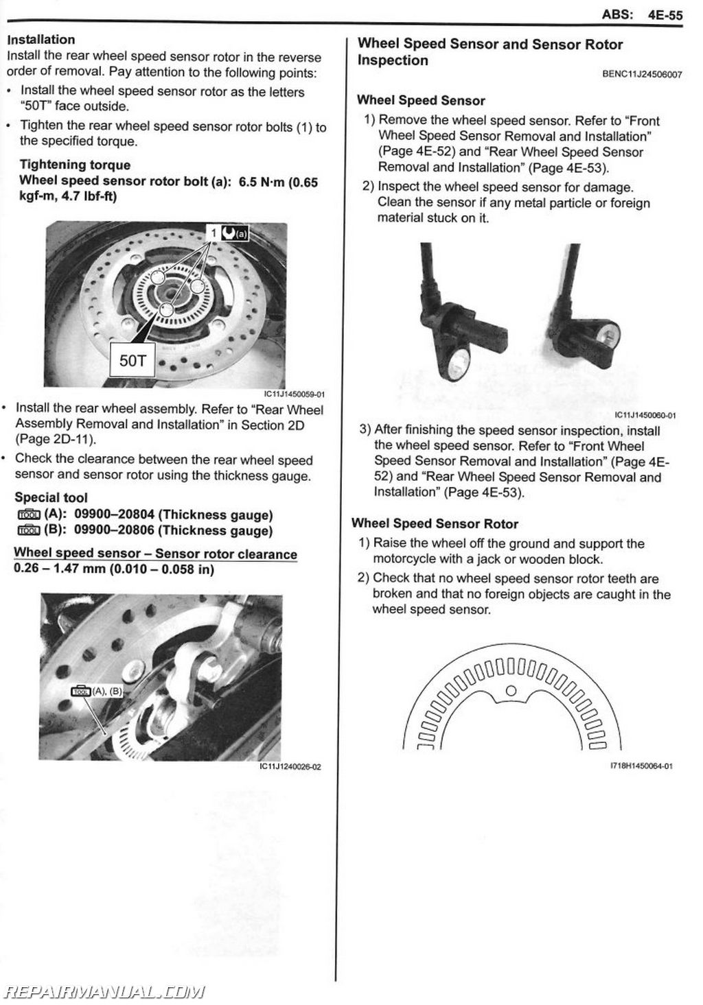
Rear Wheel Speed Sensor Rotor Removal
and Installation
Wheel Speed Sensor and Sensor Rotor
Inspection
ABS Control Unit / HU Removal and
Installation
Specifications
Tightening Torque Specifications
Special Tools and Equipment
Special Tool
Section 5 – Transmission Transaxle
Precautions
Precautions
Precautions for Transmission I Transaxle
Manual Transmission
Diagnostic Information and Procedures
Manual Transmission Symptom Diagnosis
Repair Instructions
Transmission Components
Transmission Removal and Installation
Transmission Construction
Countershaft Gear / Driveshaft Gear
Disassembly and Assembly
Transmission Related Parts Inspection
Transmission Oil Seal / Bearing Inspection
Transmission Oil Seal / Bearing Removal and
Installation
Gear Position Switch Inspection
Gear Position Switch Removal and
Installation
Gearshift Lever Construction
Gearshift Lever Removal and Installation
Gearshift Lever Height Inspection and
Adjustment
Gearshift Shaft / Gearshift Cam Plate
Components
Gearshift Construction
Gearshift Shaft / Gearshift Cam Plate
Removal and Installation
Gearshift Linkage Inspection
Gearshift Shaft Oil Seal Removal and
Installation
Specifications
Service Data
Tightening Torque Specifications
Special Tools and Equipment
Recommended Service Material
Special Tool
Clutch
Precautions
Precautions for Clutch System
Diagnostic Information and Procedures
Clutch System Symptom Diagnosis
Repair Instructions
Clutch Lever Position Switch Inspection
Clutch Cable Inspection and Adjustment
Clutch Cable Removal and Installation
Clutch Lever Components
Clutch Lever Removal and Installation
Clutch Push Rod (Left) I Clutch Release
Camshaft Removal and Installation
Clutch Push Rod (Left) Inspection
Clutch Components
Clutch Removal
Clutch Installation
Clutch Parts Inspection
Primary Drive Gear Removal and Installation
Primary Drive Gear Inspection
Primary Drive Gear Disassembly and
Assembly
Specifications
Service Data
Tightening Torque Specifications
Special Tools and Equipment
Recommended Service Material
Special Tool
Section 6 – Steering
Precautions
Precautions
Precautions for Steering
Steering General Diagnosis
Diagnostic Information and Procedures
Steering Symptom Diagnosis
Steering I Handlebar
Repair Instructions
Handlebars Components
Handlebar Construction
Handlebars Removal and Installation
Handlebars Inspection
Steering Components
Steering Removal and Installation
Steering Related Parts Inspection
Steering System Inspection
Steering Stem Bearing Removal and
Installation
Steering Tension Adjustment
Specifications
Tightening Torque Specifications
Special Tools and Equipment
Recommended Service Material
Special Tool
Section 9 – Body and Accessories
Precautions
Precautions
Precautions for Electrical System
Component Location
Electrical Components Location
Wiring Systems
Schematic and Routing Diagram
Wiring Diagram
Wiring Harness Routing Diagram
Specifications
Service Data
Tightening Torque Specifications
Special Tools and Equipment
Recommended Service Material
Lighting Systems
Repair Instructions
Headlight Construction
Headlight Components
Headlight Removal and Installation
Headlight Bulb and Position Light Bulb
Replacement
Headlight Beam Adjustment
Rear Lighting System Construction
Rear Combination Light Components
Rear Combination Light Removal and
Installation
Rear Combination Light Bulb Replacement
License Plate Light Components
License Plate Light Removal and Installation
License Plate Light Bulb Replacement
Front Turn Signal Light Construction
Turn Signal Light Components
Front Turn Signal Light Removal and
Installation
Rear Turn Signal Light Removal and
Installation
Turn Signal Light Bulb Replacement
Turn Signal / Side-stand Relay Inspection
Turn Signal / Side-stand Relay Removal and
Installation
Hazard Switch Inspection
Turn Signal Switch Inspection
Passing Light Switch Inspection
Dimmer Switch Inspection
Specifications
Service Data
Tightening Torque Specifications
Special Tools and Equipment
Special Tool
Combination Meter / Fuel Meter / Horn
General Description
Combination Meter System Description
Repair Instructions
Combination Meter Components
Combination Meter Removal and Installation Combination Meter Disassembly and
Assembly
Combination Meter Inspection
Engine Coolant Temperature Indicator Light
Inspection
Engine Coolant Temperature Removal and
Installation
Fuel Level Indicator Light Inspection
Fuel Level Gauge Inspection
Speedometer Inspection
Speed Sensor Removal and Installation
Speed Sensor Inspection
Oil Pressure Indicator Inspection
Oil Pressure Switch Removal and Installation
Ignition Switch Inspection
Ignition Switch Removal and Installation
Horn Inspection
Horn Removal and Installation
Freeze Indicator Light Inspection
Ambient Air Temperature Sensor Removal
and Installation
Ambient Air Temperature Sensor Inspection
Select Button Inspection
Specifications
Service Data
Tightening Torque Specifications
Special Tools and Equipment
Special Tool
Exterior Parts
Schematic and Routing Diagram
Seat Lock Cable Routing Diagram
Repair Instructions
Cowling Construction
Frame Cover Construction
Rear Fender Construction
Sport Carrier Construction
Fastener Removal and Installation
Exterior Parts Removal and Installation
Specifications
Tightening Torque Specifications
Special Tools and Equipment
Recommended Service Material
Body Structure
Repair Instructions
Body Frame Construction
Front Footrest Construction
Pillion Footrest Construction
Side-stand Construction
Specifications
Tightening Torque Specifications
Special Tools and Equipment
Recommended Service Material



 SKU: H5643
 SKU: CPP-200