Description
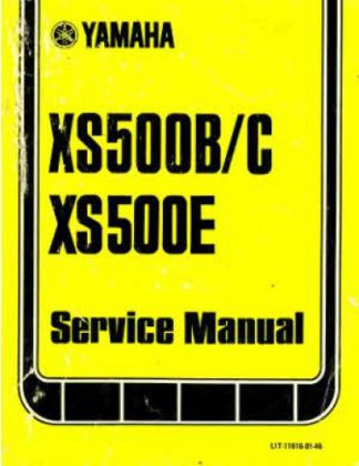
This 1975-1978 Yamaha XS500 Service Manual is a high quality reproduction of the original out of print repair manual. It is NOT a collectible but it does provide detailed service information, step-by-step repair instruction and maintenance specifications for Yamaha XS500 motorcycles. This book will help you restore and service your motorcycle.
Motorcycles Covered
1975 Yamaha XS500B repair
1976 Yamaha XS500C repair
1977 Yamaha XS500D repair
1978 Yamaha XS500E repair
Table of Contents
GENERAL
MACHINE identification
FEATURES
A DOHC and Eight Valves
B Over-square, 180°-phased Integratad Crankshaft
C Pressure-feed, Wet Sump System
D Air Cleaner with Sub-chamber
E Twin CV-carburetors
F Large diameter Headlight
G IC Regulator
H Stoplight Outage
GENERAL SPECIFICATIONS
EXTERNAL VIEW
PERIODIC MAINTENANCE INTERVALS
LUBRICATION INTERVALS
SPECIAL FEATURES
DOHC 8-VALVE AND SPECIAL ALLOY VALVE SEAT ENGINE
A Double Overhead Camshaft (DOHC)
B Use of eight valves
C Specially alloy valve seats
HIGH-SPEED TYPE, 180°-PHASED, INTEGRATED CRANKSHAFT AND ViBRATIONLESS SYSTEM;
A In order to attain the best possible engine performance at high speed operation, a high-speed type, 180°-phased, integrated crankshaft has been adopted,
B Vibrationless System
WET SUMP LUBRICATION SYSTEM
AIR CLEANER WITH SUB CHAMBER
CV CARBURETOR
A Features
B Key to Symbols
C Construction and Operation
D Operation and Adjustment
E Forced Operation of Throttle Cable
WELL-BALANCED 5-SPEED TRANSMISSION
HIGH-TENSION STEEL TUBE DOUBLE-CRADLE FRAME
DISC BRAKE
A Construction
B Operation
C Brake Lever
D Master Cylinder
ADJUSTABLE REAR SUSPENSION
IC REGULATOR
STOPLIGHT OUTAGE
INSPECTION AND ADJUSTMENT
ENGINE – INSPECTIONS AND ADJUSTMENTS
Compression Pressure Measurement
A Measuring Conditions
B Measurement
Tappet Clearance Adjustment
Balancer Chain Adjustment
Carburetor Adjustment
A Idle-Speed Adjustment
B Throttle Valve Adjustment
C Checking Synchronization of Throttle Valves
Engine Oil and Oil Filter Replacement
A Engine oil should be replaced after the first 250 miles of operation and then, after 1,000 miles and thereafter, every 2,000 miles
B Oil Filter Element Replacement
Air Cleaner Cleaning
Clutch Adjustment
Pre-tightening Cylinder Holding Nuts
Engine Troubleshooting
A The engine will not start or is hard to start
B Poor idling and low speed operation
C Poor high speed operation
D The engine lacks power
E Overheating
F-Exhaust smoke
CHASSIS – INSPECTIONS AND ADJUSTMENTS
Inspection of fuel petcocks and fuel tank filter cap air hole
Front Brake – Inspections and Adjustments
Rear Brake Inspections and Adjustments
Drive Chain – Adjustments and Lubrication
Chain Tension Adjustment
Lubrication
Tire Pressure
Rear Arm shaft Greasing
Brake Shaft Greasing
ELECTRICAL EQUIPMENT – INSPECTIONS AND ADJUSTMENTS
Ignition Timing – Inspection and Adjustment
A Ordinary Adjustment
B Adjustments required when the following parts are replaced crankcase, crankcase cover (R), governor shaft, driven gear, cam chain sprocket assembly
Spark Plug inspection
Battery Inspection
Stop Switch Adjustment
RETIGHTENING BOLTS AND NUTS
ENGINE DISASSEMBLY
Engine – Removal and Installation
Cylinder Head Cover and Camshaft Case – Disassembly
Cylinder Head Disassembly
Cylinder and Piston Removal
Crankcase Cover (Right) Disassembly
Clutch Disassembly
Kick Shaft, Pump Primary Gear and Idle Gear • Removal
Shift Levers 2 and 3 – Removal
Generator, Balancer Chain and Starting Motor – Removal
Crankcase Disassembly
Transmission Gears and Crankshaft Assembly – Removal
Tachometer Drive Gear Axle Removal
Balancer Shaft Removal
Oil Pump Disassembly
Shift Forks and Shift Cam – Removal
INSPECTION AND MEASUREMENT
Camshaft Case and Camshafts
Intake and Exhaust Camshafts
Valve Rocker Arms
Valve, Valve Spring, Valve Guides and Valve Seats –
Cylinder Head
Cylinder Block
Pistons and Piston Rings –
Crankshaft and Connecting Rods
Friction Plates and Clutch Plates –
Clutch Housing Spacer
Clutch Spring and Push Rod
Shift Cam, Shift Forks and Cam Follower Pin
Oil Pump
ENGINE ASSEMBLY
Engine Section
Shift Forks and Shift Cam – Inspection
Shift Shaft Assembly and Shift Levers 2 and 3 – Installation – Oil Pump Assembly
Balancer and Tachometer Drive Gear Axle – Assembly
Transmission Gear Assembly
Shifter Adjustment
Crankshaft Assembly
Upper Crankcase Assembly
Generator, Balancer, and Starter Chain – Assembly
Kick Shaft, Pump Primary Drive Gear and Idle Gear – Installation
Clutch Assembly
Primary Drive Gear, Breaker Shaft, and Chain Sprocket Cam
Chain – Assembly
Right Crankcase Cover Installation
Pistons and Cylinders • Assembly
Cylinder Head Assembly
Camshaft Case Assembly
Camchain Joint
Tappet Clearance Adjustment
Ignition Timing Adjustment
Cylinder Head Cover Installation
Filling with Engine Oil
Engine Mounting
Ignition Timing Adjustment using Timing Light
Retightening Cylinder Holding Nuts and Cylinder Head Bolts and Nuts
CV Carburetors — Disassembly, Inspection and Adjustment
CHASSIS
Front Wheel Removal
Disc Brake Disassembly
Disc Brake Inspection
Disc Brake – Assembly and Inspection
Front Forks – Inspection and Assembly
Rear Wheel Removal
Rear Arm – Installation
Rear Wheel Sprocket Removal
Clutch Damper Clutch Replacement
Rear Cushion
Rear Brake Diagram
ELECTRICAL EQUIPMENT
Ignition System
Charging System
A AC Generator
B IC Voltage Regulator
C Silicon Rectifier
D Charging System Inspection
Starting System
A Starting Motor
Symbols of Lights
A Stoplight Outage
B Headlight
C Flasher Relay – Circuit and Operation
D Checking Other Lighting and Signal System


 SKU: CPP-293
 SKU: M410
 SKU: M415

