Description
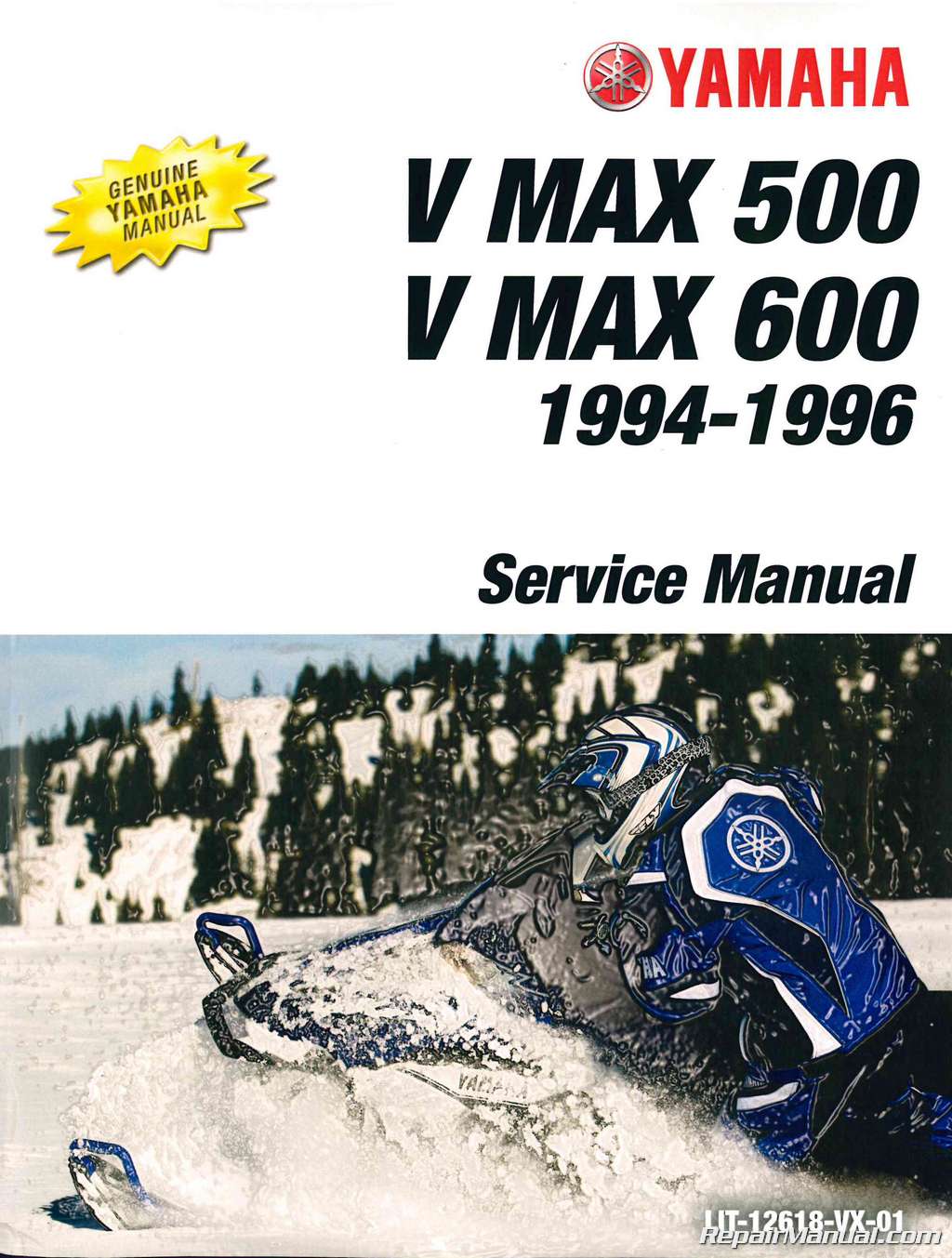
This Official 1994-1996 Yamaha V Max 500 VX500 And V Max 600 VX 600 Snowmobile Factory Service Manual provides detailed service information, step-by-step repair instruction and maintenance specifications for:
1994 Yamaha V Max 500 VX500 Snowmobiles
1994 Yamaha V Max 600 VX 600 Snowmobiles
1995 Yamaha V Max 500 VX500 Snowmobiles
1995 Yamaha V Max 600 VX 600 Snowmobiles
1996 Yamaha V Max 500 VX500 Snowmobiles
1996 Yamaha V Max 600 VX 600 Snowmobiles
1994-1996 Yamaha V Max 500 VX500 And V Max 600 VX 600 Snowmobile Service Manual Table of Contents
General Information
Periodic Inspection And Adjustment
Chassis
Power Train
Engine Overhaul
Cooling System
Carburetion
Electrical
Specifications
Optional Kit
1994-1996 Yamaha V Max 500 VX500 And V Max 600 VX 600 Snowmobile Service Manual Index of Topics
Chapter 1 General Information
Machine Identification
Frame Serial Number
Engine Serial Number
Important Information
Preparation For Removal And Disassembly
All Replacement Parts
Gaskets, Oil Seals, And O-rings
Lock Washers/plates And Cotter
Pins
Bearings And Oil Seals
Circlips
Special Tools
Fortune Up
For Engine Service
For Power Train Service
For Electrical Service
Chapter 2 Periodic Inspections And Adjustments
Introduction
Periodic Maintenance Table
Engine
Sparkplug
Oil Pump
Oil Filter Inspection
Fuel Line Inspection
Fuel Filter Inspection
Cooling System
Carburetor Synchronization
Engine Idle Speed Adjustment
Throttle Cable Adjustment
Throttle Override System (TORS) Check
Starter (choke) Cable Adjustment
Power Train
Drive V-belt
Engagement Speed Check
Brake Adjustment
Brake Pad Inspection
Drive Chain
Track Tension Adjustment
Slide Runner Inspection
Chassis
Ski/ski Runner
Steering System
Headlight Beam Adjustment
Lubrication
Tuning
Carburetor Tuning
Clutch Tuning
Gearing Selection
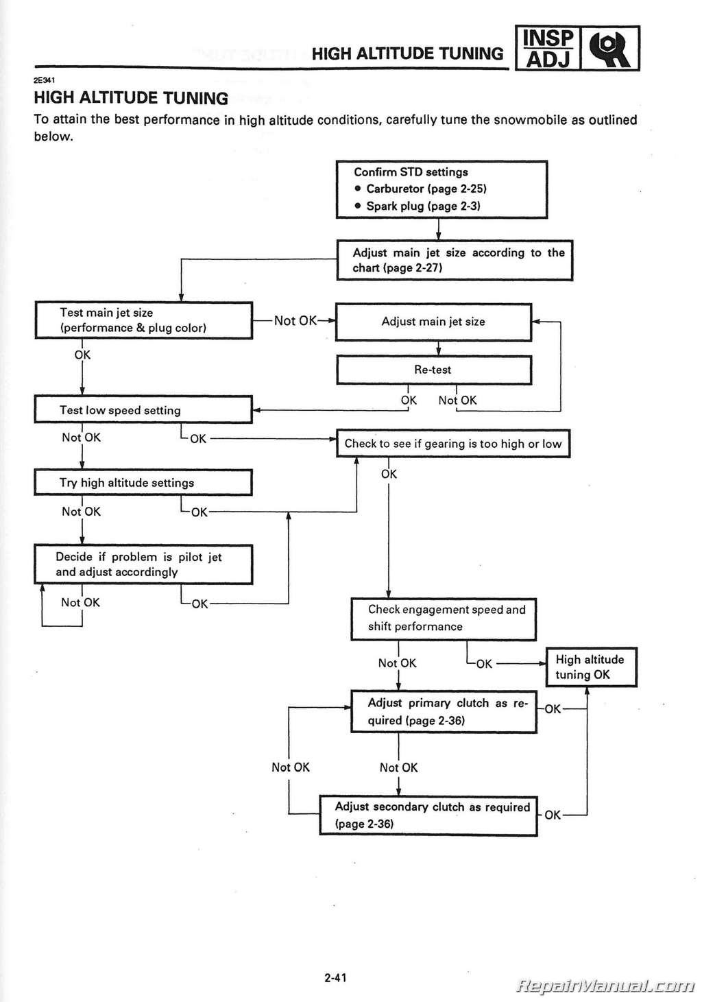
High Altitude Tuning
Chapter 3 Chassis
Steering
Removal
Inspection
Installation
Ski
Removal
Inspection
Installation
Front Suspension
Removal
Inspection
Installation
Chapter 4 Power Train
Primary Sheave And Drive V-belt
Removal
Disassembly
Inspection
Assembly
Installation
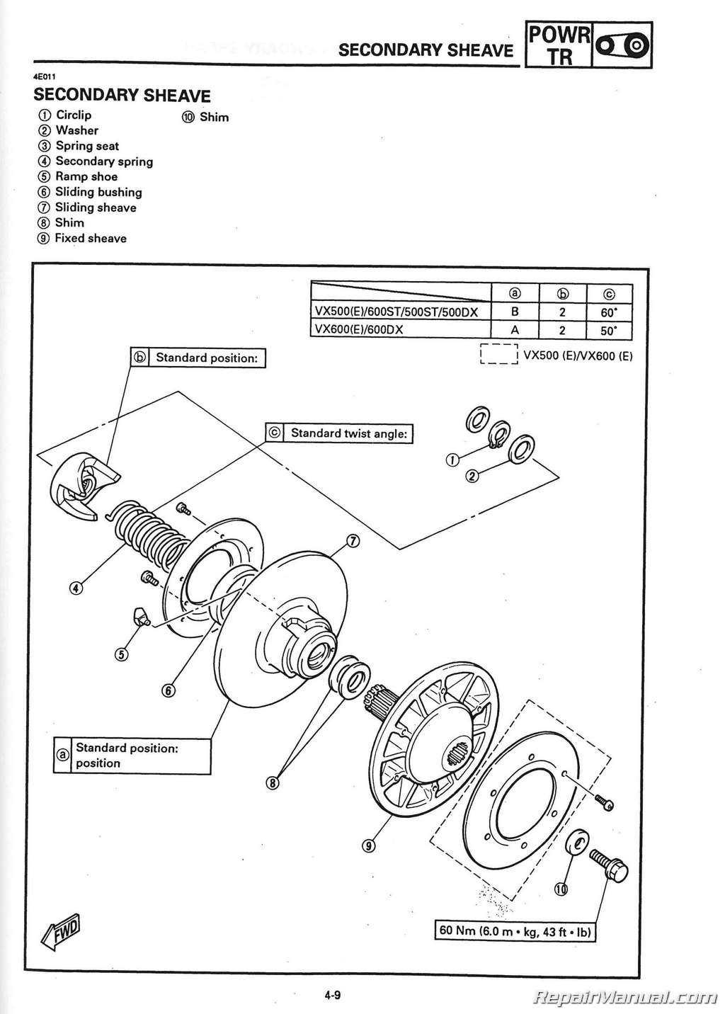
Secondary Sheave
Removal
Disassembly
Inspection
Assembly
Installation
Sheave Distance And Offset Adjustment
Drive Chain Housing And Jackshaft
Removal
Inspection
Installation
Drive Chain Housing And Jackshaft
Removal
Inspection
Installation
Brake
Removal
Disassembly
Inspection
Assembly And Installation
Slide Rail Suspension
Removal
Disassembly
Inspection
Assembly
Installation
Front Axle And Track
Removal
Inspection
Installation
Chapter 5 Engine Overhaul
Engine Removal
Battery Leads (for Electric Model)
Hoses
Cable And Leads
Water Pump Housing
Starter Motor (for Electric Model)
Engine Removal
Disassembly
Oil Pump
Water Pump
CDI Magneto
Cylinder Head And Cylinder
Piston
Crankcase And Crankshaft
Inspection And Repair
Cylinder Head
Cylinder And Piston
Piston Rings
Piston Pin
Crankshaft
Reed Valve And Intake Manifold
Engine Assembly And Adjustment
Crankcase And Crankshaft
Piston, Cylinder And
Cylinder Head
Piston
Cylinder And Cylinder Head
Cdi Magneto
Water Pump
Oil Pump
Remounting Engine
Recoil Starter
Removal
Disassembly
Inspection
Assembly And Installation
Chapter 6 Cooling System
Coolant Flow
Cooling Line
Cooling System
Removal
Inspection
Installation
Chapter 7 Carburetion
Carburetor
Removal
Disassembly
Inspection
Assembly
Fuel Level Adjustment
Fuel Pump
Operation Check
Chapter 8
Electrical
Circuit Diagram
Electrical Component
Electrical Starting System (for Electric Model)
Circuit Diagram
Troubleshooting
Main Switch (for Electric Model)
Starter Motor
Troubleshooting
Battery
Charging Coil
Ignition System
Circuit Diagram
Troubleshooting
Spark Plug Cap
Ignition Coil
Source Coil
Spark Plug
Throttle Override System (TORS)
Handlebar Switch (right)
Carburetor Switch
Main Switch
Lighting System
Circuit Diagram
Troubleshooting
Bulb (s)
Headlight Beam Switch
Signal System
Circuit Diagram
Troubleshooting
Tail/brake Light Bulb
Brake Light Switch
Reverse Switch
Back Buzzer
Thermo System
Oil Level Switch
Fuel Sender
Condenser (non Electric Model)
Grip Warmer System
Circuit Diagram
Troubleshooting
Grip And Thumb Warmer Coil
Grip Warmer Switch
Grip Warmer Coil
Chapter 9
Specifications
General Specifications
Maintenance Specifications
Engine
Power Train
Chassis
Electrical
General Torque Specifications
Definition Of Units
Cable Routing
Chapter 10 Optional Kit
Reverse Gear Kit10-1
Starting Motor Kit10-5
Battery Installation10-7
VX500(E)/500ST/500DX/600(E)/600ST/600DX Wiring Diagram


 SKU: LIT-12628-02-54
 SKU: LIT-12628-02-69
 SKU: LIT-12618-BR-01
