Description
This Three Volume Set, Case 210B 310 Wheel Tractor, 310 310C Crawler, 430 530 Construction King Forklift and 430 530 Construction King Tractor Loader Backhoe manual provides detailed service information, step-by-step repair instruction and maintenance specifications. This reproduction manual is a copy of the original out of print factory manual.
Model “23” Loader and Backhoe Table of Contents
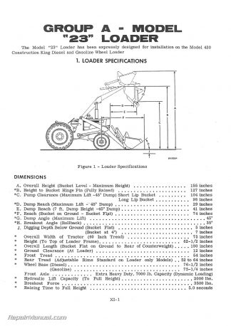
Group a – Model “23” Loader
1. Specifications.
2. Serial Number Location
3. Lubrication
4. Hydraulic System
5. Hydraulic Pumps
6. Control Valve.
7. Hydraulic Cylinders.
8. Servicing Loader.
Group B – Model “23” Backhoe
1. Specifications
2. Serial Number Location
3. Lubrication
4. Hydraulic System.
5. Control Valve
6. Hydraulic Cylinders .
7. Servicing Backhoe .
Group C – Testing Hydraulic Valves and Circuits
1. Loader Main Relief Valve
2. Backhoe Relief Valves.
3. Checking Secondary Relief Valves with Hand Pump
4. Hydraulics Testing with “flowmeter”
5. Pump and System Component Testing
Group D – Schematic Illustrations
Group E — Hydraulic System Trouble Shooting Chart .
Group F — Torque Specifications.
310 and 310 C Crawler Tractors Table of Contents
Group a – General Information
1. Specifications
2. Lubrication
3. Torque Specifications.
Group B – Engine.
1. Specifications
2. Service Information.
Group C – Fuel and Electrical Systems
1. Electrical System.
2. Fuel System
Group D – Clutch.
1. Removing Engine and Associated Parts . . . .
2. Removing Clutch Housing.
3. Servicing Clutch Pressure Plate.
4. Disassembling Clutch Housing
5. Installing Clutch.
Group E – Driveshaft.
1. Removing Driveshaft.
2. Replacing Universal Joint Bearings
3. Installing Driveshaft.
Group F – Transmission. Differential. Final Drive.
And P.T.O. Belt Pulley.
1. Lubrication.
2. Differential
3. Transmission
4. Final Drive.
5. P.T.O. and Belt Pulley (optional)
Group G – Track and Suspension
1. Removing Track
2. Disassembling Track Suspension
3. Front Idler’
4. Track Rollers.
5. Track Support Idler (optional)
6. Assembling Track Suspension
7. Track Chain.
8. Installing Track
210 B and 310 Series Wheel Tractors and 310 and 310 C Crawler Tractors
Table of Contents
Group a – General Information
Group B – Oil and Reservoirs 1. Oil 2. Reservoirs
Group C — Filters 1. Filter Service Problems 2. Cleaning Hydraulic Oil Filter
Group D — Pump and Drive 1. Pump 2. Front Mounted Pump Drive
Group E – Cylinders 1. Disassembling the Cylinder 2. Inspecting the Cylinder 3. Assembling the Cylinder
Group F – Valves 1. Dual-Control Valve 2. Diversion Valve (crawler Only) 3. Special Relief Valve 4. Backhoe Flow Control Valve 5. Backhoe Control Valve
Group G – Hoses
Group H — Flow Charts
Model “31” Loader and Backhoe
Table of Contents
Group a – Model ”31” Loader.
1. Loader Specifications.
2. Loader Serial Number Location.
3. Loader Lubrication
4. Loader-Backhoe Hydraulic System.
5. Hydraulic Pump .
Hydrecopump]
Commercial Pump.
6. Checking Hydraulic Pump with Flowmeter
7. Loader Control Valve
8. Checking and Adjusting Loader Main Relief Valve Pressure
9. Loader Hydraulic Cylinders .
10. Servicing Loader
Group B – Model ”31” Backhoe
1. Backhoe Specifications
2. Backhoe Serial Number Location
3. Backiioe Lubrication
4. Backhoe – Loader Hydraulic System.
5. Backhoe Hydraulic Control Valve.
Hydreco Backhoe Control Valve
Commercial Backhoe Control Valve .
6. Checking and Adjusting Backhoe Main Relief Valve Pressure
7. Backhoe Secondary (load) Relief Valves
8. Swing Criss-Cross Relief Valve (external).
9. Boom Drop Controls . 7
10. Hydraulic Cylinders.
11. Servicing Backhoe
Group C – Schematic Illustrations.
Group D – Hydraulic System Trouble Shooting Chart.
Model “21” Loader and Backhoe
Table of Contents Group a – Backhoe Hydraulic System
1. Oil
2. Reservoir . . .
3. Hydraulic Pump Lubrication
4. Servicing Hydraulic Pump
O. Servicing Backhoe Control Valve
6. Checking Secondary Relief Valve Pressure
7. Adjusting Main Relief Valve
Group B – Loader Hydraulic System
1. Oil
2. Reservoir . . .
3. Servicing Loader Control Valve
4. Servicing Single Action Lift Cylinder
5. Servicing Bucket Dump Cylinder
This description includes the information in volume 1 – there are 2 other volumes also included in this set.
 SKU: JS-CA-S-S-SERIES
 SKU: JS-CA-S-1200TK
 SKU: JS-CA-P-W26