Description
This 210 page, Bobcat 970 G&D Skid Steer Factory Service Manual provides detailed service information, step-by-step repair instruction and maintenance specifications for Bobcat M-970 Loaders.
Table of Contents
Operation of Bobcat M-970 Loader
Loader Service And Maintenance
Air Cleaner Service
Belly Pan
Bobtach System
Changing Engine Oil
Control Lever Lock
Cooling System Service
Cylinder Head Retorquing
Enclosure Latches
Enclosure Removal And Reinstallation
Engine Hood
Engine Lubrication Service
Fan Belt Adjustment
Fuel Pickup Tube
Fuel Specifications
Fuel System Service
Fuel Tank
Two Stage Air Cleaner With Aspirator
Hoisting The M-970
Initial 25 – 50 Hour Service
Injector Service
Lift Arm Replacement
Oil Filter Replacement
Operator Enclosure Tilt Control
Preventive Maintenance Schedule
Recommended Oil Specifications
Reworking Lift Arm Assembly
Side Panel And Grill Removal
Tire Maintenance
Transporting The M-970
Venting Fuel System
Electrical Service
Alternator Checks
Battery Installation
Battery Problems
Instrument Panels
Regulator Checks
Replacing Headlamps
Wiring Harness
Hydraulic And Hydrostatic Service
Assembling Servo Pistons
Assembling The Cylinder Block
Attaching Control Link
Attaching Servo Piston Assemblies To Swash Plate
Basic Operating Principle Of Hydraulic System
Charge Pump Removal And Reinstallation
Checking Charge Pressure
Check Valve Removal And Reinstallation
Control Valve Service
Disassembly Instructions
Disassembly Procedure
Displacement Control Valve Removal And Reinstallation
Filter Service
Hydraulic Control Valve Bank
Hydraulic Cylinder Inspection And Service
Hydraulic Fluid Cooler Service
Hydraulic Leaks
Hydraulic Pump Service
Hydraulic Service
Hydraulic Test Kit
Hydrostatic Charge Pump
Hydrostatic Circuitry
Hydrostatic Motor Manifold Block Service
Hydrostatic Motor Removal And Reinstallation
Hydrostatic Operation Principle
Hydrostatic Pump And Motor Control Adjustment
Hydrostatic Pump And Motor Displacement Control Valve
Hydrostatic Pump Removal And Reinstallation
Installing Bearing Plate
Installing Control Assembly
Installing Drive Shaft
Installing End Cap And Charge Pump
Installing Front Cover And Gasket
Installing Shaft Seal
Installing Servo Sleeves
Installing Spring Guide
Installing Swash Plate
Installing Thrust Plate
Installing Trunnions
Overhaul Of Hydrostatic Pump And Motor
Placing Valve Plate On End Cap
Pressing Cone Of Rear Bearing Into Shaft
Reassembly Procedure
Removal Of Pump Or Motor From Vehicle
Removal Of Seal From Pump Or Motor
Removing Charge Pump And Check Valves
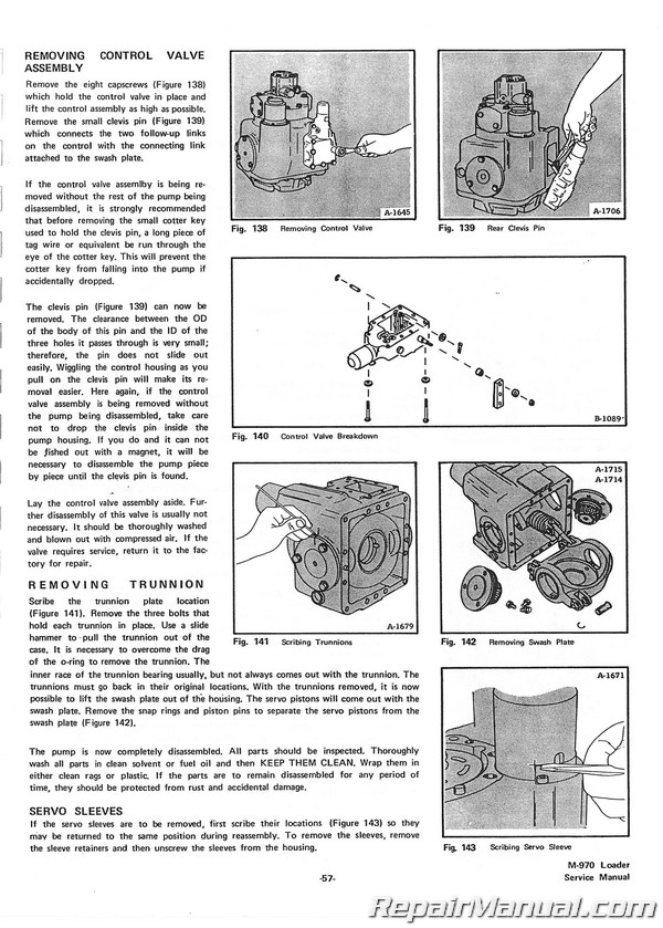
Removing Control Valve Assembly
Removing Drive Shaft
Removing End Cap
Removing Front Cover
Removing Pistons And Slipper Retainer
Removing Rear Bearing
Removing Slipper Retainer Guide
Removing Spring Guide And Cylinder Block
Removing Thrust Plate
Removing Trunnions
Removing Valve Plate And Bearing Plate
SAE Connection (37° Flare)
SAE Split Flange Connection (Bolt)
SAE Straight Thread O-ring Seal
Seal Reinstallation
Mechanical Drive
Axle Carrier Reinstallation
Axle Carrier Removal
Chaincase Service
Clark Reduction Gearcase
Clutch Service
Disassembling A Funk Gearcase
Disassembling The Axle Carrier
Final Drive Chain
Final Drive Chain Removal
Final Drive Idler Repair
Final Drive Re Installation
Gearcase Mounting
Gearcase Removal
Power Transfer Chain Adjustment
Reassembling A Clark
Reduction Gearcase
Reassembling A Funk Gearcase
Reassembling The Axle Carrier
Reduction Gearcase
Transfer Chaincase Removal
Perkins Engine Service
Assemble Pistons To Connecting Rods
Balance Unit Service
Breather Assembly
Checking The Timing Gear Backlog
Checking Valve Timing
Cooling System Service
Crankcase Ventilation
Crankshaft And Main Bearings
Crankshaft Service
Cylinder Head Gasket
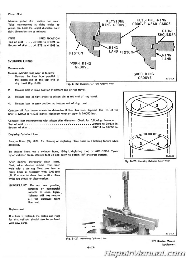
Cylinder Liners
Engine Description
Engine Number
Engine Removal (Perkins)
Flywheel Service
Fuel System Service
Injector Service
Installing Main Bearings And Thrust Washers
Installing Pistons And Connecting Rods To Cylinder Bore
Installing New Pistons
Introduction
Lubrication Oil Sump
Lubrication System
Main Bearing And Thrust Washer Removal
Milling Of Cylinder Head
Reassemble Cylinder Head
Reinstalling Cylinder Heads
Reinstalling Tappets And Camshaft
Reinstalling Timing Case Cover
Removing And Reinstalling Camshaft Gear
Removing And Reinstalling Fuel Pump Gear
Removing And Reinstalling Idler Gear And Hub
Removing Camshaft And Tapper
Removing Cylinder Head
Removing Pistons And Connecting Rods
Removing Timing Case Cover
Removing And Reinstalling Timing Case
Renewing Crankshaft Front And Seals
Renewing Cylinder Liners
Rocker Shaft Assembly
Smoke Diagnosis Chart
Valve Removal
Valve Service
Troubleshooting Perkins
Continental Engine Section
Assembling Oil Seals In Filler
Block And Oil Guard
Camshaft
Crankshaft And Main Bearings
Crankshaft End Play
Cooling System Service
Cylinder Head
Engine Description
Engine Removal
Engine Repair And Overhaul
Fuel System
Flywheel And Flywheel Housing
Ignition System
Information For Ordering Parts
Jute Type Oil Seals
Lubrication System
Neoprene Oil Seal
Oil Pump
Pistons And Connecting Rod Service
Pistons And Piston Pins
Preparing Cylinder Walls For
Regrinding Or Reboring
Reassembling Engine
Tappets
Timing Gears
Troubleshooting Continental Engine
Valve Service
Technical Data Limits And Clearances
Forms
Specifications
Technical Data:
Continental
Perkins
Time Required For Service
Loader Torque Specifications
John Deere Engine Service
Balanced Shafts
Camshaft
Cooling System
Crankshaft, Main Bearings And Flywheel
Cylinder Block Liners Pistons And Rods
Cylinder Head And Valves
Cylinder Head Valves, Camshaft And Timing Gear Train
Cylinder Heads And Valve Train Parts
Installation
Detailed Tune-up Procedures
Engine Break-in Instructions
(After Overhaul)
Engine Tune-up
Fuel System
Lubrication System
Preliminary Engine Testing
Special Tools
Specifications
Timing Gear Train
Valve Clearance Adjustment
Valve Train


