Description
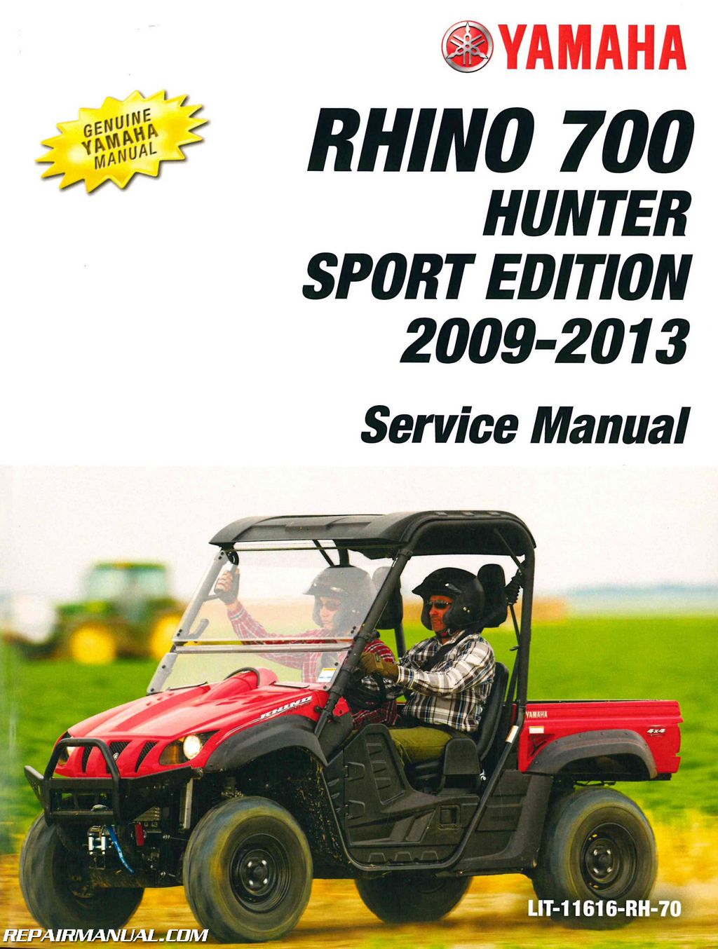
This Official 2009 – 2013 Yamaha YXR700 Rhino Side X Side Factory Service Manual provides detailed service information, step-by-step repair instruction and maintenance specifications for 2009, 2010, 2011, 2012, 2013 Yamaha YXR700 Rhino Side X Side UTVs including Hunter Sport Editions.
Service Manual Table Of Contents
General Information
Specifications
Periodic Checks And Adjustments
Engine
Cooling System
Fuel Injection System
Drive Train
Chassis
Electrical
Troubleshooting
Service Manual Index of Topics
Chapter 1 General Information
Vehicle Identification
Vehicle Identification Number
Model Label
Features
Outline Of The Fi System
Fi System
Instrument Functions
Important Information
Preparation For Removal And Disassembly
Replacement Parts
Gaskets, Oil Seals And O-rings
Lock Washers/plates And Cotter Pins
Bearings And Oil Seals
Circlips
Checking The Connections
Special Tools
Chapter 2 Specifications
General Specifications
Engine Specifications
Chassis Specifications
Electrical Specifications
Tightening Torques
Engine Tightening Torques
Chassis Tightening Torques
How To Use The Conversion Table
Lubrication Points And Lubricant Types
Engine
Coolant Flow Diagrams
Oil Flow Diagrams
Cable Routing
Chapter 3 Periodic Checks And Adjustments
Introduction
Periodic Maintenance Chart For The Emission Control System General Maintenance And Lubrication Chart
Engine
Adjusting The Valve Clearance
Adjusting The Throttle Cable
Checking The Spark Plug
Checking The Ignition Timing
Measuring The Compression Pressure
Checking The Engine Oil Level
Changing The Engine Oil
Cleaning The Air Filter Element
Checking The Throttle Body Joint
Checking The Fuel Hose
Checking The Breather Hoses
Checking The Coolant Level
Changing The Coolant
Checking The Cooling System
Checking The Coolant Temperature Warning Light
Checking And Replacing The V-belt
Checking The Exhaust System
Cleaning The Spark Arrester
Chassis
Adjusting The Brake Pedal
Adjusting The Parking Brake
Checking The Brake Fluid Level
Checking The Front Brake Pads
Checking The Rear Brake Pads
Checking The Parking Brake Pads
Checking The Brake Hoses And Brake Pipes
Bleeding The Hydraulic Brake System
Adjusting The Select Lever Shift Rod
Adjusting The Brake Light Switch
Checking The Final Gear Oil Level
Changing The Final Gear Oil
Checking The Differential Gear Oil
Changing The Differential Gear Oil
Checking The Constant Velocity Joint Dust Boots
Checking The Steering System
Adjusting The Toe-in
Adjusting The Front Shock Absorbers
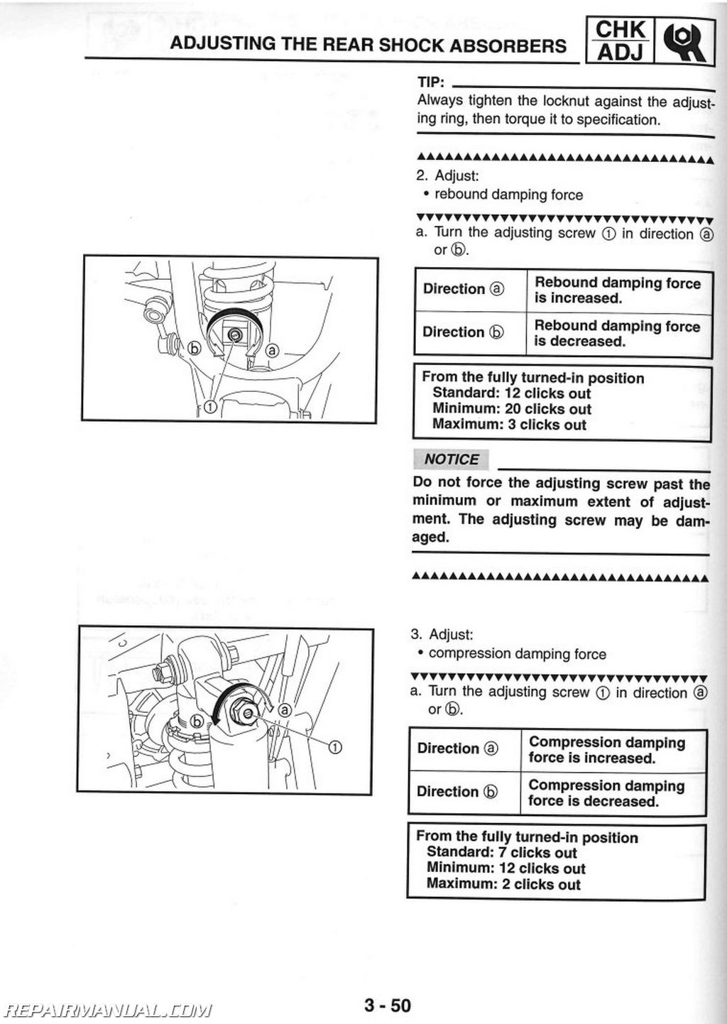
Adjusting The Rear Shock Absorbers
Checking The Tires
Checking The Wheels
Checking And Lubricating The Cables
Lubricating The Pedal, Etc
Electrical System
Checking And Charging The Battery
Checking The Fuses
Adjusting The Headlight Beams
Changing The Headlight Bulbs
Changing The Tail/brake Light Bulb
Chapter 4 Engine
Engine Removal
V-belt Cooling Ducts, Muffler And Exhaust Pipes
Installing The V-belt Cooling Ducts
Shift Arm
Hoses And Leads
Engine Mounting Bolts
Installing The Engine
Cylinder Head
Removing The Cylinder Head
Checking The Camshaft Sprocket
Checking The Tappet Covers
Checking The Timing Chain Tensioner
Checking The Cylinder Head
Installing The Cylinder Head
Rocker Arms And Camshaft
Removing The Rocker Arms And Camshaft
Checking The Camshaft
Checking The Decompression System
Checking The Rocker Arms And Rocker Arm Shafts
Installing The Camshaft And Rocker Arms
Valves And Valve Springs
Removing The Valves And Valve Springs
Checking The Valves And Valve Springs
Installing The Valves And Valve Springs
Cylinder And Piston
Removing The Piston
Checking The Cylinder And Piston
Checking The Piston Rings
Checking The Piston Pin
Installing The Piston And Cylinder
AC Magneto
Removing The Ac Magneto Rotor
Checking The Stator Coil And Crankshaft Position
Sensor
Checking The Starter Clutch
Checking The Torque Limiter
Installing The Ac Magneto Rotor
Balancer Gears And Oil Pump Gears
Removing The Balancer Driven Gear And Oil Pump
Driven Gear
Checking The Oil Pump Drive
Checking The Balancer Drive
Installing The Balancer Drive Gear, Balancer Driven Gear, And Oil Pump Driven Gear
Primary And Secondary Sheaves
Primary Sheave
Secondary Sheave
Removing The Primary And Secondary Sheaves
Disassembling The Secondary Sheave
Checking The Primary Sheave
Checking The Secondary Sheave
Assembling The Primary Sheave
Assembling The Secondary Sheave
Installing The Primary And Secondary Sheaves
Clutch
Removing The Clutch
Checking The Clutch
Installing The Clutch
Crankcase
Timing Chain And Oil Filter
Crankcase
Crankcase Bearings
Separating The Crankcase
Checking The Timing Chain And Guide
Checking The Relief Valve
Checking The Bearings
Checking The Crankcase
Assembling The Crankcase
Installing The Shift Lever
Crankshaft And Oil Pump
Oil Pump
Removing The Crankshaft
Checking The Oil Pump
Checking The Oil Strainer
Checking The Crankshaft
Assembling The Oil Pump
Installing The Crankshaft
Transmission
Drive Axle
Removing The Transmission
Checking The Shift Forks
Checking The Shift Drum
Checking The Transmission
Checking The Secondary Shaft
Assembling The Shift Fork Assembly
Installing The Transmission
Middle Gear
Middle Drive Shaft
Middle Driven Shaft
Removing The Middle Drive Shaft
Removing The Middle Driven Shaft
Checking The Pinion Gears
Selecting Middle Drive And Driven Gear Shims
Installing The Bearing And Oil Seals
Installing The Middle Driven Shaft
Installing The Middle Drive Shaft
Measuring The Middle Gear Backlash
Chapter 5 Cooling System
Radiator And Coolant Reservoir
Checking The Radiator
Installing The Radiator
Thermostat
Checking The Thermostat
Installing The Thermostat
Water Pump
Disassembling The Water Pump
Checking The Water Pump
Assembling The Water Pump
Oil Cooler
Checking The Oil Cooler
Chapter 6 Fuel Injection System
Fuel Injection System
Circuit Diagram
Ecu Self-diagnostic Function
Self-diagnostic Function Table
Troubleshooting Chart
Diagnostic Mode
Troubleshooting Details
Checking The Intake Air Pressure Sensor
Checking The Intake Air Temperature Sensor
Air Filter Case And Air Intake Duct
Installing The Air Intake Duct And Air Filter Case
Fuel Pump And Fuel Tank
Removing The Fuel Tank
Removing The Fuel Pump
Checking The Fuel Pump Body
Checking The Rollover Valve
Installing The Fuel Pump
Installing The Fuel Hose
Throttle Body
Removing The Throttle Body Assembly
Checking The Fuel Injector
Checking The Throttle Body
Installing The Throttle Body Assembly
Checking The Fuel Pump And Pressure Regulator
Operation
Checking And Adjusting The Throttle Position Sensor
Chapter 7 Drive Train
Troubleshooting
Checking Noises
Troubleshooting Chart
Front Constant Velocity Joints, Differential Gear And Drive Shaft
Disassembling The Front Constant Velocity Joints
Disassembling The Universal Joint
Removing The Differential Gear Assembly
Checking The Front Constant Velocity Joints
Checking The Differential Gears
Checking The Differential Gear Motor
Assembling The Front Constant Velocity Joints
Assembling The Differential Gears
Assembling The Universal Joint
Measuring The Differential Gear Lash
Adjusting The Differential Gear Lash
Checking The Differential Gear Operation
Rear Constant Velocity Joints, Final Drive Gear And Drive Shaft
Disassembling The Rear Constant Velocity Joints
Assembling The Rear Constant Velocity Joints
Disassembling The Final Gear Case
Removing The Final Drive Roller Bearings
Installing The Final Drive Roller Bearings
Positioning The Final Drive Pinion Gear And Ring
Gear
Checking The Drive Shaft
Checking The Final Gear Case
Measuring And Adjusting The Final Gear Lash
Assembling The Final Gear Case
Chapter 8 Chassis
Seats, Enclosure, Hood And Cargo Bed
Front Guard And Hood
Seats, Rear Console And Instrument Panels
Removing The Steering Wheel
Installing The Steering Wheel
Side Doors
Panels And Front Console
Removing The Side Panels
Install The Side Panels
Cargo Bed
Skid Plates
Installing The Rear Skid Plate
Enclosure And Seat Belts
Installing The Enclosure
Front And Rear Wheels
Front Wheels
Rear Wheels
Checking The Wheels
Checking The Wheel Hubs
Checking The Brake Discs
Installing The Wheel Hubs
Installing The Wheels
Front And Rear Brakes
Front Brake Pads
Rear Brake Pads
Replacing The Front And Rear Brake Pads
Brake Master Cylinder
Checking The Master Cylinder
Assembling The Brake Master Cylinder
Installing The Brake Master Cylinder
Front Brake Caliper
Rear Brake Calipers
Disassembling The Front And Rear Brake Calipers
Checking The Front And Rear Brake Calipers
Assembling The Front And Rear Brake Calipers
Installing The Front And Rear Brake Calipers
Parking Brake
Parking Brake Pads
Replacing The Parking Brake Pads
Parking Brake
Parking Brake Disc
Checking The Parking Brake
Checking The Parking Brake Disc
Assembling The Parking Brake
Pedal Assembly
Steering System
Steering Shaft And Steering Assembly
Disassembling The Steering Assembly
Checking The Steering Joint
Checking The Steering Assembly
Assembling The Steering Assembly
Installing The Steering System
Tie-rod And Steering Knuckle
Removing The Steering Knuckles
Checking The Tie-rods
Checking The Steering Knuckles
Front Arms And Front Shock Absorbers
Removing The Front Arms
Checking The Front Arms
Handling The Front Shock Absorbers And Gas Cylinders
(for Models Equipped With Gas-oil Damper Shock Absorbers)
Disposing Of A Front Shock Absorber And Gas Cylinder
(for Models Equipped With Gas-oil Damper Shock Absorbers)
Checking The Front Shock Absorbers
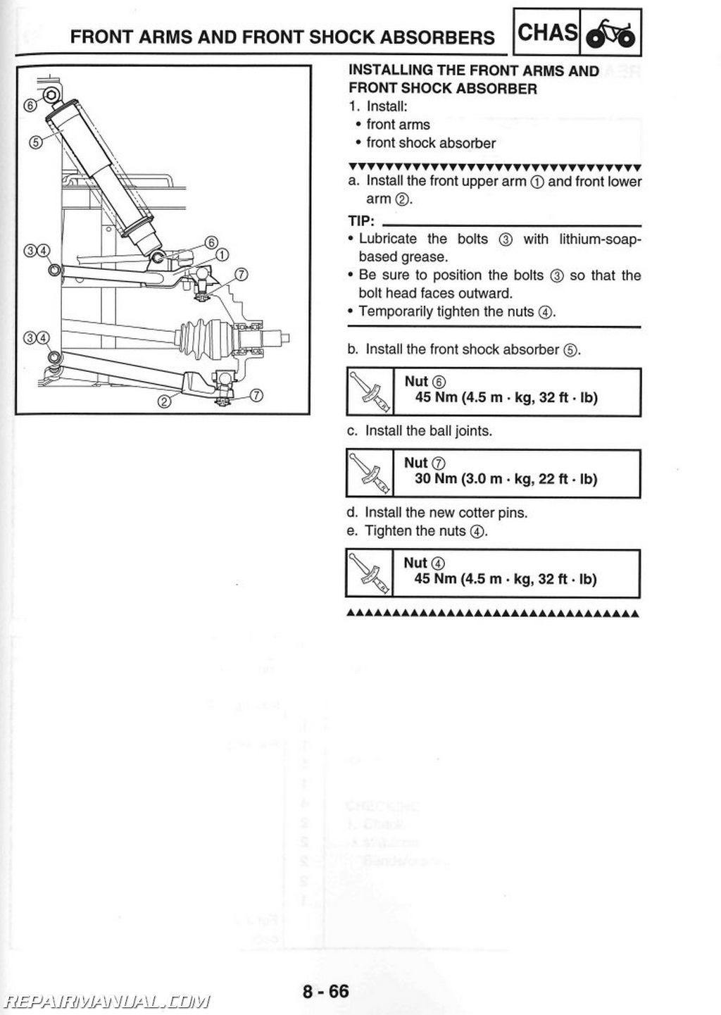
Installing The Front Arms And Front Shock Absorber
Rear Knuckle And Stabilizer
Checking The Rear Knuckles
Checking The Stabilizer
Rear Arms And Rear Shock Absorber
Checking The Rear Arms
Handling The Rear Shock Absorbers And Gas Cylinders
(for Models Equipped With Gas-oil Damper Shock Absorbers)
Disposing Of A Rear Shock Absorber And Gas Cylinder
(for Models Equipped With Gas-oil Damper Shock Absorbers)
Checking The Rear Shock Absorbers
Installing The Rear Arms And Rear Shock Absorber
Chapter 9 Electrical
Electrical Components
Checking Switch Continuity
Checking The Switches
Checking The Bulbs And Bulb Sockets
Types Of Bulbs
Checking The Condition Of The Bulbs
Checking The Condition Of The Bulb Sockets
Ignition System
Circuit Diagram
Troubleshooting
Electric Starting System
Circuit Diagram
Starting Circuit Operation
Troubleshooting
Starter Motor
Checking The Starter Motor
Assembling The Starter Motor
Charging System
Circuit Diagram
Troubleshooting
Lighting System
Circuit Diagram
Troubleshooting
Checking The Lighting System
Signaling System
Circuit Diagram
Troubleshooting
Checking The Signaling System
Cooling System
Circuit Diagram
Troubleshooting
Fuel Pump System
Circuit Diagram
Troubleshooting
2WD/4WD Selecting System
Circuit Diagram
Troubleshooting
Chapter 10 Troubleshooting
Starting Failure/hard Starting
Fuel System
Electrical System
Compression System
Poor Idle Speed Performance
Poor Idle Speed Performance
Poor Medium And High-speed Performance
Poor Medium And High-speed Performance
Faulty Drive Train
Faulty Gear Shifting
Hard Shifting
Shift Lever Does Not Move
Jumps Out Of Gear
Faulty Clutch Performance
Engine Operates But Vehicle Will Not Move
Clutch Slipping
Poor Starting Performance
Poor Speed Performance
Overheating
Overheating
Overcooling
Cooling System
Faulty Brake
Poor Braking Effect
Shock Absorber Malfunction
Malfunction
Unstable Handling
Unstable Handling
Lighting System
Headlight Does Not Come On
Bulb Burnt Out


