Description
This Official 1996-2000 Polaris Sportsman 335 500 ATV Factory Service Manual provides detailed service information, step-by-step repair instruction and maintenance specifications for 1996-2000 Polaris Sportsman 500 and the 1999-2000 Polaris Sportsman 335 ATVs.
1996-2000 Polaris Sportsman 335 500 ATV Service Manual Coverage
1996 Polaris Sportsman 500
1997 Polaris Sportsman 500
1998 Polaris Sportsman 500
1999 Polaris Sportsman 500
2000 Polaris Sportsman 500
1999 Polaris Sportsman 335
2000 Polaris Sportsman 335
1996-2000 Polaris Sportsman 335 500 ATV Service Manual Table of Contents
Chapter 1 General
Chapter 2 Maintenance
Chapter 3 Engine
Chapter 4 Fuel System, Carburetion
Chapter 5 Body, Suspension
Chapter 6 PVT System
Chapter 7 Final Drive
Chapter 8 Transmission
Chapter 9 Brakes
Chapter 10 Electrical
1996-2000 Polaris Sportsman 335 500 ATV Service Manual Index of Topics
A
A-Arm Replacement, 5.7
Air Box Sediment Tube, Maintenance, 2.28
Air Filter Service, 2.28
Auxiliary Brake Adjustment/Hydraulic, 2.42, 9.6
Auxiliary Brake Adjustment/Mechanical, 9.6
Auxiliary Brake Testing/Mechanical, 9.6
Auxiliary Shut Off Switch Testing, 10.40
AWD Armature Plate Inspection, 7.10
AWD Electric Hub Engagement, 7.2
AWD Magnetic Coil Installation, 7.8
AWD Magnetic Coil Removal, 7.8
AWD Operation, 7.2
AWD Switch Testing, 10.41
AWD Testing, 10.29
B
Battery Charging, 10.14
Battery Inspection/Removal, 10.12
Battery Installation, 10.12
Battery Maintenance, 2.24
Battery Service, Initial, 10.11
Battery Storage, 10.14
Battery Terminal Bolts, 10.11
Battery Testing, 10.12
Bleed Hole Inspection, 3.8
Body Assembly Exploded View, 5.2
Brake Bleeding, 9.7-9.8
Brake Caliper Assembly, Front, 9.20
Brake Caliper Assembly, Rear, 9.26-9.27
Brake Caliper Disassembly, Front, 9.18-9.19
Brake Caliper Exploded View, Front, 9.22
Brake Caliper Exploded View, Rear, 9.29-9.31
Brake Caliper Inspection, Front, 9.19
Brake Caliper Installation, Front, 9.21
Brake Caliper Removal, Front, 9.18
Brake Caliper Removal, Rear, 9.25-9.26
Brake Disc Inspection, Front, 9.16
Brake Disc Inspection, Rear, 9.28
Brake Disc Removal / Replacement, Front, 9.17
Brake Fluid Change, 9.7-9.8
Brake Fluid Level, 2.41
Brake Hose/Fitting Inspection, 2.41
Brake Light Switch Testing, 10.45
Brake Noise Troubleshooting, 9.3
Brake Pad Adjustment, Front, 9.15
Brake Pad Application, 9.2
Brake Pad Assembly, Front, 9.15-9.16
Brake Pad Inspection, 2.41
Brake Pad Installation, Rear, 9.24
Brake Pad Kits, 9.2
Brake Pad Removal, Front, 9.14
Brake Pad Removal, Rear, 9.23
Brake System Operation, 9.4
Brake Troubleshooting, 9.32
Brakelight Lamp Replacement, 10.3
Breather Filter Maintenance, 2.29
Breather Hose, 2.29
C
Cam Chain Drive Sprocket Installation, 3.70
Cam Chain Tensioner Inspection, 3.21
Cam Chain Tensioner Installation, 3.79
Cam Chain Tensioner Removal, 3.20
Cam Chain/Camshaft Installation, 3.76
Cam Chain/Tensioner Blade Removal, 3.52-3.53
Camber & Caster, 2.36
Camshaft Inspection, 3.28
Camshaft Removal, 3.25-3.26
Camshaft Timing, 3.76-3.78
Carburetor Assembly, 4.13
Carburetor Cleaning, 4.11
Carburetor Disassembly, 4.9-4.10
Carburetor Exploded View, 4.8
Carburetor Float Bowl Draining, 2.22
Carburetor Float Height Adjustment, 4.14
Carburetor Float System, 4.7
Carburetor Fuel Level Testing, 4.15
Carburetor Inspection, 4.12
Carburetor Main System, 4.7
Carburetor Needle and Seat Testing, 4.15
Carburetor Operation, 4.5
Carburetor Pilot System, 4.6
Carburetor Starter System, 4.6
Carburetor System Function, 4.4
Carburetor Venting Systems, 4.4
CDI Output Test, 10.9
Charging System Testing, 10.15-10.17
Choke Adjustment, 2.16
Clutch Alignment, 6.19
Clutch Offset, 6.19
Cold Weather Kits, 2.3
Combustion Chamber, 3.35
Compression Release Installation, 3.27
Compression Release Removal/Inspection, 3.27
Compression Test, 2.23
Controls and Routings, 2.44-2.45
Coolant Bleeding Procedure, 2.27
Coolant Level Inspection, 2.27
Coolant Strength, 2.26
Cooling System Floses, 2.26
Cooling System Overview, 2.26
Cooling System Pressure Test, 3.8
Cooling System Troubleshooting, 3.88
Counter Balancer Installation, 3.67
Counter Balancer Shaft End Play Adjustment, 3.65
Counter Balancer Shaft Removal/Inspection, 3.58
Cover/Panel Removal, 5.3
Crankcase Assembly, 3.67
Crankcase Bearing Inspection, 3.61
Crankcase Bearing Installation, 3.62
Crankcase Disassembly, 3.50
Crankcase Inspection, 3.62
Crankcase Separation, 3.54
Cranking Output Test, 10.9
Crankshaft End Play Insp/Adjustment, 3.63-3.64
Crankshaft Installation, 3.67
Crankshaft Removal/Inspection, 3.59
Crankshaft Straightening, 3.60
CV Joint Handling Tips, 7.13, 7.36
Cylinder Cleaning, 3.49
Cylinder Head Assembly, 3.40-3.41
Cylinder Head Disassembly, 3.32-3.33
Cylinder Head Exploded View, EH50PL, 3.30
Cylinder Head Exploded View, ES33PF, 3.29
Cylinder Head Inspection, 3.31
Cylinder Head Installation, 3.75
Cylinder Head Reconditioning, 3.36
Cylinder Head Removal, 3.29-3.31
Cylinder Head Warpage, 3.32
Cylinder Honing, 3.49
Cylinder Inspection, 3.45-3.46
Cylinder Installation, 3.73-3.74
Cylinder Removal/Inspection, 3.42-3.43
D
Decal Replacement, 5.12
Decimal Equivalent Chart, 1.20
Drive Belt Removal/Inspection, 6.18
Drive Belt Tension, 6.17
Drive Clutch Assembly, 6.16-6.17
Drive Clutch Bushing Service, 6.20-6.23
Drive Clutch Disassembly, 6.13-6.15
Drive Clutch Exploded View, 6.12
Drive Clutch Inspection, 6.11
Drive Clutch Operation, 6.2
Driven Clutch Assembly, 6.27
Driven Clutch Bushing Service, 6.28-6.31
Driven Clutch Disassembly, 6.24-6.26
Driven Clutch Operation, 6.2
Dual Hydraulic Caliper Bleeding, 9.5
E
EBS Drive Clutch Bushing Service, 6.40-6.41
EBS Drive Clutch Inspection, 6.35-6.36
EBS Drive One Way Clutch Inspection, 6.35
EBS Driven Clutch Bushing Service, 6.42-6.43
EBS Driven Clutch Disassembly, 6.37-6.39
EBS Driven One Way Clutch Inspection, 6.37
EBS Exploded View, 6.34
EBS Moveable Sheave Bushing Inspection, 6.36
EBS System, Operation Guidelines, 6.33
EBS Theory Of Operation, 6.32
Electrical Tools, 10.1
Electronic Speedometer Overview, 10.33
Electronic Speedometer Testing, 10.34-10.38
Electronic Speedometer Wiring Diagram, 10.39
Engine Accessible Components, 3.10
Engine Break in Period, 3.12
Engine Designation Numbers, 1.1
Engine Exploded View, EH50PL, 3.19
Engine Exploded View , ES33PF, 3.18
Engine Fastener Torque, 2.23
Engine Fastener Torque Patterns, 3.2
Engine Installation Notes, 3.12
Engine Lubrication, 3.13
Engine Mounts, 2.23
Engine Removal, 3.11
Engine Serial Number Location, 1.1
Engine Service Data, 3.4-3.7
Engine to Frame Ground, 2.25
Engine Troubleshooting, 3.86-3.87
ETC Switch Adjustment, 2.20
ETC Switch Testing, 10.29-10.30
ETC Theory Of Operation, 10.27
Exhaust System, Maintenance, 2.40
Exhaust Valve Adjustment, 2.34-2.35
F
Fan Control Circuit, 10.44
Fan Control Circuit Testing, 10.43
Fan Control Switch Bypass Test, 10.43
Fan Motor Current Draw Test, 10.45
Flywheel Identification, 10.6
Flywheel Installation, 3.80
Flywheel Removal, 3.51
Frame, Nuts, Bolts, Fasteners, 2.47
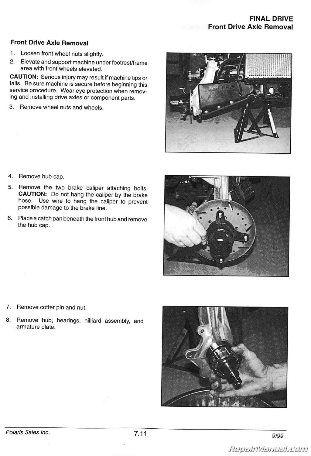
Front Axle Installation, 7.12
Front Axle Removal, 7.11-7.12
Front Axle Seal Sleeve Replacement, 7.17
Front Drive Axle Exploded View, 7.15
Front Drive Shaft Boot Replacement, 7.13-7.14
Front Gearcase Assembly, 7.26-7.29
Front Gearcase Disassembly, 7.22-7.25
Front Gearcase Exploded View, 7.30
Front Gearcase Identification, 7.23
Front Gearcase Installation, 7.29
Front Gearcase Removal, 7.22
Front Hub Bearing Adjustment, 7.5
Front Hub Disassembly, 7.3
Front Hub Engagement Limiter, 10.32
Front Hub Exploded View, 7.6
Front Hub Fluid Change, 2.39
Front Hub Fluid Level Inspection, 2.39
Front Hub Seal Replacement, 7.7
Front Hub/Wheel Bearing Installation, 7.4
Front Prop Shaft Removal, 7.18
Front Strut Assembly, 5.9
Front Strut Ball Joint Replacement, 5.11
Front Strut Casting Seal Replacement, 7.16
Front Strut Weldment Replacement, 5.10
Fuel Filter Maintenance, 2.21
Fuel Flow Diagram, 4.3
Fuel Line Maintenance, 2.21
Fuel Pump Exploded View, 4.17
Fuel Pump Service, 4.16
Fuel System/Carb Troubleshooting, 4.18-4.19
Fuel Tank Assembly, 4.2
G
Gear Position Switch Testing, 10.46
Gear Selector Switch Testing, 10.41
Gear Shift Boot Replacement, 8.5
Gear Shift Selector Assembly, 8.4
Gear Shift Selector Disassembly, 8.2-8.3
Gear Shift Selector Installation, 8.5
Gear Shift Selector Removal, 8.2
Glossary of Terms, 1.23-1.24
H
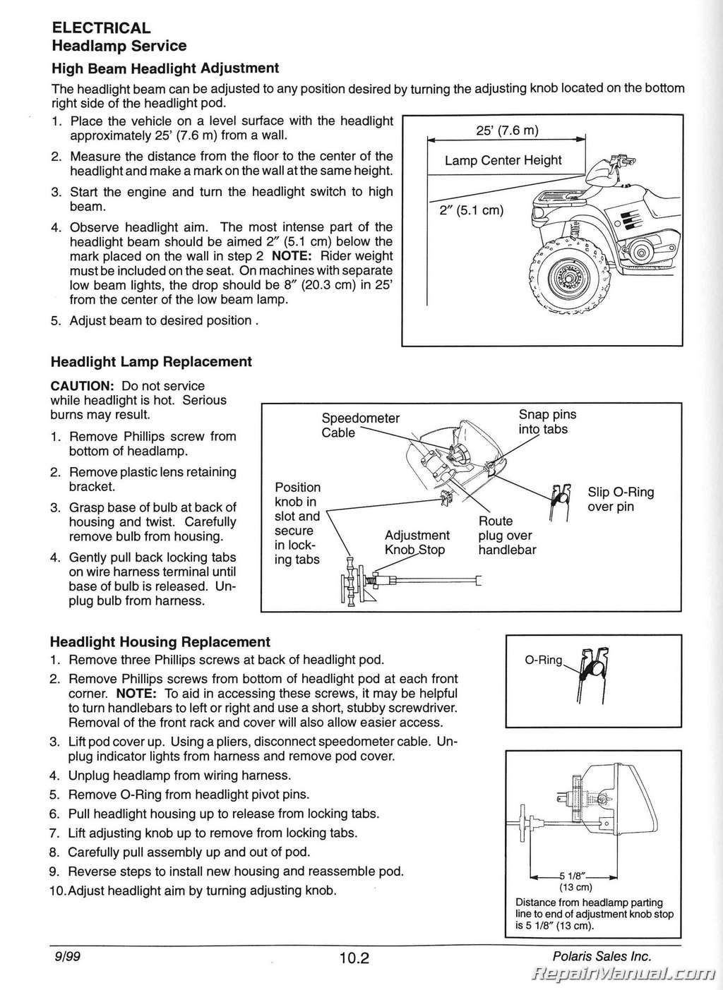
Headlamp Service, 10.2
Headlamp Switch Testing, 10.45
Headlight Adjustment, 10.2
Headlight Housing Replacement, 10.2
Headlight Pod Assembly Exploded View, 5.4
Hilliard Clutch Disassembly/Inspection, 7.9
Honing to Oversize, 3.49
Hot Light Circuit Lamp/Test, 10.42
Hot Light Circuit Operation, 10.42
Hot Light Sensor Testing, 10.42
I
Idle Speed Adjustment, 2.19
Ignition System Components, 10.7
Ignition System Troubleshooting, 10.8,10.10
Ignition Timing, 2.25
Ignition Timing Curve, 10.5
Indicator Lamp Service, 10.3
Intake Valve Adjustment, 2.34
J
Jet Part Numbers-Mikuni, 4.3 Jetting Guidelines, 4.1
K
Key Switch Testing, 10.40
L
Load Test, 10.13
Lubricants & Part Numbers, 2.4
Lubricants, Recommended, 2.3
Lubrication Chart, 2.5-2.8
Lubrication, Front Gearcase, 2.10-2.11
Lubrication, Gearcase Quick Reference, 2.9
Lubrication, Transmission, 2.12
M
Main Jet Selection, 4.1 Maintenance Chart, Periodic, 2.1-2.2 Master Cylinder Assembly, 9.11-9.12 Master Cylinder Disassembly, 9.9-9.10 Master Cylinder Inspection, 9.11 Master Cylinder Installation, 9.13 Model & Serial Number Location, 1.1 Model & VIN Identification, 1.1
N
Neutral Light Operation, 10.45
o
Oil/Filter Change, Engine, 2.31-2.32
Oil Cooler Notes, 10.44
Oil Flow, EH50PL, 3.16-3.17
Oil Flow, ES33PF, 3.14-3.15
Oil Pipes Installation, 3.81
Oil Pressure Test, 3.13
Oil Pump Assembly, 3.57
Oil Pump Installation, 3.67
Oil Pump Removal/Inspection, 3.55-3.57
Oil Pump Shaft End Play, 3.66
Oil Pump Shaft Seal Installation, 3.66
One Way Valve Inspection, 3.53
One Way Valve Installation, 3.70
Output Housing (Snorkel) Assy, 8.23-8.26
Output Housing (Snorkel) Backlash Adj, 8.26-8.27
Override Button Testing, 10.40
p
Paint Codes, 1.16
Pilot Screw Adjustment, 2.18
Pilot Screw Plug Removal, 2.17
Pilot Mixture Screw Adjustment (Altitude), 4.1
Piston/Connecting Rod Inspection, 3.47
Piston Identification, 3.3
Piston Installation, 3.72
Piston Removal, 3.44
Piston Ring Installation, 3.71-3.72
Piston Ring Installed Gap, 3.48
Piston to Cylinder Clearance, 3.46
Pre-Ride Inspection, 2.2
Publication Numbers, 1.16
PVT Assembly, 6.6
PVT Disassembly, 6.4-6.5
PVT Operation, 6.2
PVT Overview, 6.8
PVT System Sealing & Ducting Components, 6.7
PVT, Drying, 6.3
PVT, Maintenance, 6.3
PVT, Overheating, 6.3
PVT Troubleshooting, 6.44-6.45
R
Radiator Cap Pressure Test, 3.8
Radiator Level Inspection, 2.27
Radiator, Maintenance, 2.26
Rear Drive Shaft Assembly, Dual CV, 7.40
Rear Drive Shaft CV Service, 7.41
Rear Drive Shaft Disassembly, 7.38
Rear Drive Shaft Disassembly, Dual CV, 7.39
Rear Drive Shaft Installation, 7.37
Rear Drive Shaft Removal, 7.36
Rear Drive Shaft U-Joint Alignment, 7.42
Rear Hub Assembly, 7.35
Rear Hub Disassembly, 7.34
Rear Hub Installation, 7.33
Rear Hub/Bearing Carrier Removal, 7.31-7.32
Rear Suspension Exploded View, 5.8
Recoil Assembly, 3.84
Recoil Disassembly/Inspection, 3.82-3.83
Recoil Draining, 2.30
Rocker Arm/Shaft Inspection, 3.23-3.24
Rocker Arm/Shaft Removal, 3.22
Rocker Shaft/Rocker Arm Assy Installation, 3.81
S
Shift Weights, 6.10
Side Panel Removal, 5.5
Spark Plug Maintenance, 2.25
Spark Plug Troubleshooting, 3.85
Special Tools, Body/Steering/Suspension, 5.1
Special Tools, PVT, 6.1
Specific Gravity Test, 10.13
Specifications, Brake Caliper, 9.1
Specifications, Cooling System, 3.9
Specifications, Drive Clutch Spring, 6.9
Specifications, Model, 1.2-1.15
Specifications, Speed Limiter, 10.26
Specifications, Torque, Brake, 9.1
Specifications, Torque, Engine, 3.1
Specifications, Torque, Final Drive, 7.1
Specifications, Torque, PVT, 6.1
Specifications, Torque, Standard, 1.17
Specifications, Torque, Transmission, 8.1
Speed Limiter System, Theory Of Operation, 10.27
Speed Limiter Troubleshooting, 10.28
Spider Removal, 6.14
Starter Drive Installation, 3.80
Starter Drive Removal/Inspection, 3.50
Starter Drive Service, 10.25
Starter Motor Armature Testing, 10.23
Starter Motor Assembly, 10.24
Starter Motor Brush Insp/Replmt, 10.21-10.22
Starter Motor Disassembly, 10.20-10.21
Starter Solenoid Bench Test, 10.25
Starter Switch Testing, 10.40
Starter System Troubleshooting, 10.18-10.19
Stator Installation, 3.79-3.80
Stator Removal, 3.51
Steering Assembly Exploded View, 5.6
Steering Maintenance, 2.36
Steering Post Assembly, 5.12
Suspension Preload Adjustment, 2.43
Suspension, Front, Inspection, 2.43
Suspension, Rear, Inspection, 2.43
T
Taillight Lamp Replacement, 10.3
Tap Drill Chart, 1.22
Tensioner Blade Installation, 3.70
Thermostat Installation, 3.81
Throttle Cable Adjustment, 2.20
Throttle Operation, 2.16
Tie Rod Inspection, 2.36
Timing Check Procedures, 10.4
Tire Inspection, 2.47
Tire Pressure, 2.47
Tire Tread Depth, 2.47
Toe Alignment, 2.37-2.38
Torque Conversion Table, 1.18-1.19
Transmission Assembly, 8.23-8.34
Transmission Center Shaft Bushing Inst, 8.23
Transmission Disassembly, 8.14-8.22
Transmission I.D. Location, 1.1
Transmission Installation, 8.10-8.13
Transmission Linkage Adjustment, 2.13-2.15
Transmission Removal, 8.6-8.9
Transmission Tensioner Installation, 8.32
Transmission Troubleshooting, 8.36
Transmission, Exploded View, 8.35
u
Unit of Measure Conversion Table, 1.21
U-Joint Assembly, 7.20-7.21
U-Joint Disassembly, 7.19-7.20
U—Joint Inspection, 7.38
V
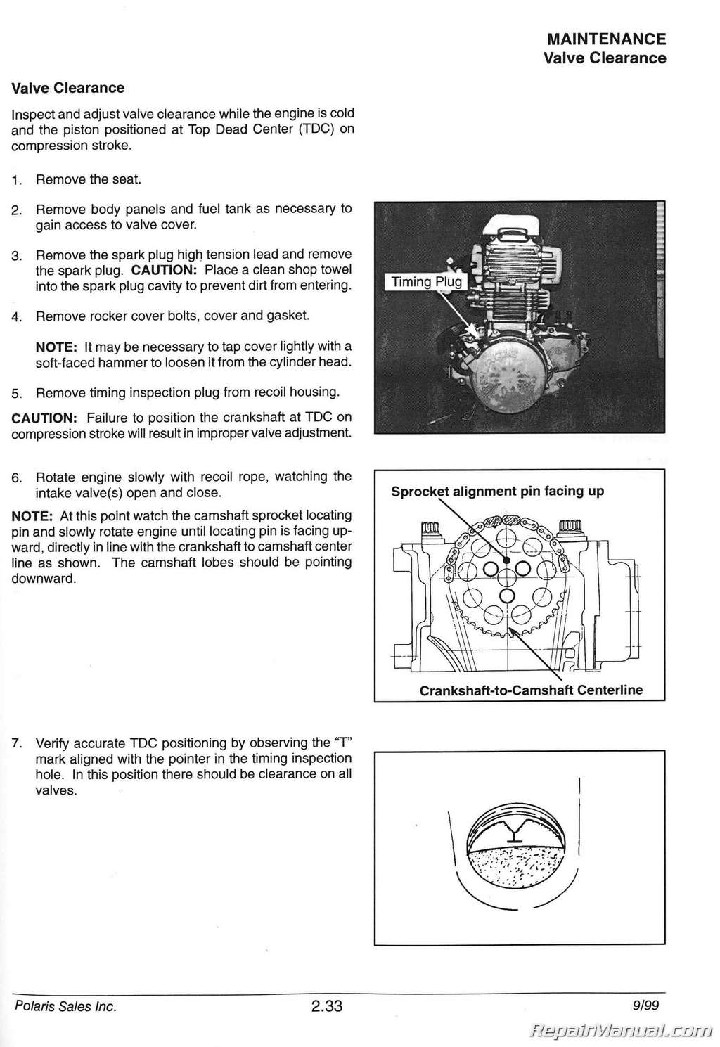
Valve Clearance, 2.33
Valve Guide Removal/Installation, 3.36
Valve Inspection, 3.34-3.35
Valve Seal Testing, 3.41
Valve Seat Inspection, 3.36
Valve Seat Reconditioning, 3.37-3.40
Vent Line Maintenance, 2.21
Voltage Drop Test, 10.18
Voltage Test Open Circuit, 10.12
w
Water Pump Mechanical Seal Installation, 3.68
Water Pump Mechanical Seal Removal, 3.61
Water Pump Mechanical Seal Removal, Engine Installed, 3.68-3.69
Water Pump Shaft Oil Seal, 3.61
Wheel Inspection, 2.46
Wheel Installation, 2.46
Wheel Removal Front or Rear, 2.46
Wiring Diagram, 1996,10.47
Wiring Diagram, 1997,10.48
Wiring Diagram, 1998,10.49
Wiring Diagram, 1999, Sportsman 335,10.50
Wiring Diagram, 1999, Sportsman 500,10.51
Wiring Diagram, 2000, Sportsman 335,10.52
Wiring Diagram, 2000, Sportsman 335(Late), 10.53
Wiring Diagram, 2000, Sportsman 500,10.54


