Description
This 167 page, 1964-1967 Hodaka Ace 90 Service Manual is a reproduction of the original, out of print manual. This manual provides detailed service information, step-by-step repair instruction and maintenance specifications for 1964-1967 Hodaka Ace 90 motorcycles. The Hodaka Industrial Co. Ltd. has been building engines and transmissions for the motorcycle industry for many years. From 1951 to 1963 they produced engines in displacements ranging from 50cc to 500cc, including 500cc professional racing engines. In 1963, Pacific Basin Trading Company designed a complete motorcycle for Hodaka to manufacture for the American market. The keynote feature of Hodaka design was ease of maintenance and repair procedures. The Hodaka motorcycle is simplicity personified, requiring but a minimum of special tools and man hours to complete normal repairs. In order to assist the owner or mechanic to complete necessary maintenance and/or repairs, PABATCO has compiled this workshop manual. A thorough study of this text prior to beginning work will effect a considerable saving in time and, possibly, money. This workshop manual is dedicated to keeping Hodaka performance at factory-new standards.
1964-1967 Hodaka Ace 90 Service Manual Coverage: 1964, 1965, 1966, 1967 Hodaka Ace 90 motorcycles
1964-1967 Hodaka Ace 90 Service Manual Table of Contents
Introduction
Foreword
Table Of Contents
Table Of Illustrations
I Modification History
Ii Two Strokes Basic Principles
Iii General Maintenance
Iv Brakes /
1 Adjusting The Front Brake
2 Adjusting The Rear Brake
3 Adjusting The Brake Cam Levers
4 Adjusting The Stoplight Switch
5 Lubrication
6 Brake Drum And Shoe Service
A Removing The Rear Wheel
B Removing The Front Wheel
C Disassembling Backing Plate Assembly
D Cleaning And Inspecting Brake Components
E Reassembling The Backing Plate Components
F Remounting The Rear Wheel
G Remounting The Front Wheel
V Chain
1 Drive Chain: Minor Adjustment
2 Drive Chain: Major Adjustment
3 Adjusting The Chain Guide
4 Lubrication
5 Removing And/or Replacing Master Links
6 Service
Vi Clutch
1 Clutch Cable Adjustment
2 Clutch Lever Adjustment
3 Lubrication
A Clutch Cable Assembly
B Clutch Assembly
4 Clutch Service
A Removing Clutch Assembly
B Removing Clutch Lever From Side Cover
C Disassembling Clutch Assembly
D Cleaning And Inspecting Clutch Components
E Reassembling Clutch Assembly
F Reassembling Side Cover Assembly
G Remounting Clutch And Side Cover Assemblies
Vii Magneto / Alternator Assembly
1 Adjusting Breaker Points (timing Engine)
A Magneto Cover Removal
B Timing The Engine By Gap Setting Method
C Alternative Timing Methods
2 Lubrication
3 Tests And Checks
4 Magneto/alternator Service
A Flywheel Removal
B Magneto Frame Assembly Removal
C Disassembling Magneto Frame Components
D Cleaning And Inspecting Magneto Components
E Reassembling Magneto Frame Assembly
F Remounting Magneto Frame Assembly
G Remounting Flywheel And Magneto Cover
Viii Cylinder And Piston
1 Cylinder And Piston Service
A Cylinder Head And Cylinder Removal
B Piston Removal
C Cleaning, Inspecting, Measuring, And Fitting Operations
D Reassembling Piston Onto Connecting Rod
E Remounting Cylinder And Cylinder Head
Ix Engine Case Assembly
1 Adjusting Transmission Gear Selector System
A Trial-and-error Method
B Measurement Method
2 Lubrication •
A Engine Assembly
B Transmission Assembly
C Magneto Cover Shifter Mechanism
3 Crankcase, Crankshaft, Transmission And
Kick Starter Service
A Removing Engine Assembly From Frame
B Dismantling Engine Case Assembly
C Cleaning And Inspecting Engine Case Components
D Reassembling Crankshaft Assembly
E Reassembling Engine Case Assembly
4 Magneto Cover Shifter Assembly Service
A Disassembling Magneto Cover Assembly
B Cleaning And Inspecting For Wear
C Reassembling Magneto Cover Assembly
X Electrical System
1 Headlight Assembly
A Adjusting Headlight Beam Position
B Tests And Checks
C Service
2 Tail And Stoplight Assembly
A Tests And Checks
B Taillight Service
3 Horn
A Adjusting The Horn
B Tests And Checks
4 Main Switch
5 Wiring Diagram
6 Dimmer Switch
7 Battery
A To Prepare A New Battery For Service
B Maintenance
8 Stoplight Switch
A Maintenance
9 Fuse
10 Selenium Rectifier
A Selenium Rectifier Test
11 Spark Plug
A Heat Ranges
B Numbering System For Heat Range
C Length (reach)
D Electrode Gap
E Cleaning
F Installation
G Various Aspects Of Firing Ends
H Normal Operation
I Oil Fouled
J Carbon Fouled
K Overheating
L Whiskering
Xi Fuel System
1 Carburetor
A Starting Circuit
B Idle To Intermediate Speed Circuit
C Intermediate To High Speed Circuit
D Mixture Adjustments
E Engine Idle Speed Adjustment
F Float Level Adjustment
G Carburetor Service
2 Manifold Assembly
A Service
3 Fuel Tank Assembly
A Service
4 Fuel Cocks
A Service
5 Fuel Lines
A Service
6 Throttle Cable Assembly
A Adjustment
B Lubrication
C Service
7 Twistgrip Assembly
A Lubrication
B Service
8 Air Cleaner Assembly
A Cleaning And Lubrication
B Service
Xii Exhaust System
1 Service Frequency
2 Spark Arrester Conversion
3 Exhaust System Service
A Removing Exhaust System
B Dismantling Exhaust System
C Cleaning And Inspecting Exhaust Components
D Reassembling And Remounting Exhaust System
Xiii Frame And Suspension Components
1 Frame
A Service
2 Steering Head Bearing Assembly
A Adjusting Steering Head Bearing Play
B Lubrication
C Steering Head Bearing Service
3 Front Fork And Handlebar Assembly
A Front Fork Alignment
B Lubrication
C Fork Service
4 Rear Fork Assembly (rear Suspension)
A Service
5 Fenders And Braces
A Service
6 The Saddle (seat)
A Service
7 Brake Pedal Assembly
A Service
8 Footrest Assembly
A Service
9 Battery Bracket
A Service
10 Side Stand
11 Tool Box Assembly
12 Carrier Rack
Xiv Wheels
1 Tires
A Tire Pressure
B Inspection
C Repairing Flats
2 Wheels
A Inspection
B Lubrication
C Wheel Bearing Service
D Truing Wheels
E Lacing Wheels
F Balancing Wheels
Supplemental Specifications
Engine
Carburetor
Magneto/alternator
Clutch
Primary Drive
Transmission
Final Drive
Kick Starter
Lighting System Equipment
Frame
Front Suspension
Rear Suspension
Wheel Rims
Tires & Tubes
Brakes
Dimensions & Weight
Torque Settings
Capacities
Clearances
Compression Pressure
Performance
Timing Specifications
Ace 90 Ignition Timing
Ace 90 Transfer Port Timing
Ace 90 Exhaust Port Timing
Ace 90 Inlet Port Timing
Ace 90 Stock Engine Port Timing Diagram Conversion Table/gallon To Quart To Pint To Liter
Metric Equivalents
Length
Area
Volume
Capacity
Weight
Pressure
Conversion Factors
Conversion Chart – Cubic Inches To Cubic Centimeters
Approximate Weight Of Various Liquids
Approximate Weight Of Various Materials
Conversion Chart/fraction Inch To
Decimal Inch To Mm
Dimensions Of Popular Ball Bearings
Drill Sizes
Conversion Chart: Tire Pressures
Conversion Chart: Temperature
Hodaka Workshop Tools
Handy Formulas
Ngk Spark Plug Conversion Chart
Racing Spark Plugs
Air And Fuel Proportioning Table
1964-1967 Hodaka Ace 90 Service Manual Table of Illustrations
Piston and cylinder view
Cutaway drawing, Hodaka two-stroke engine
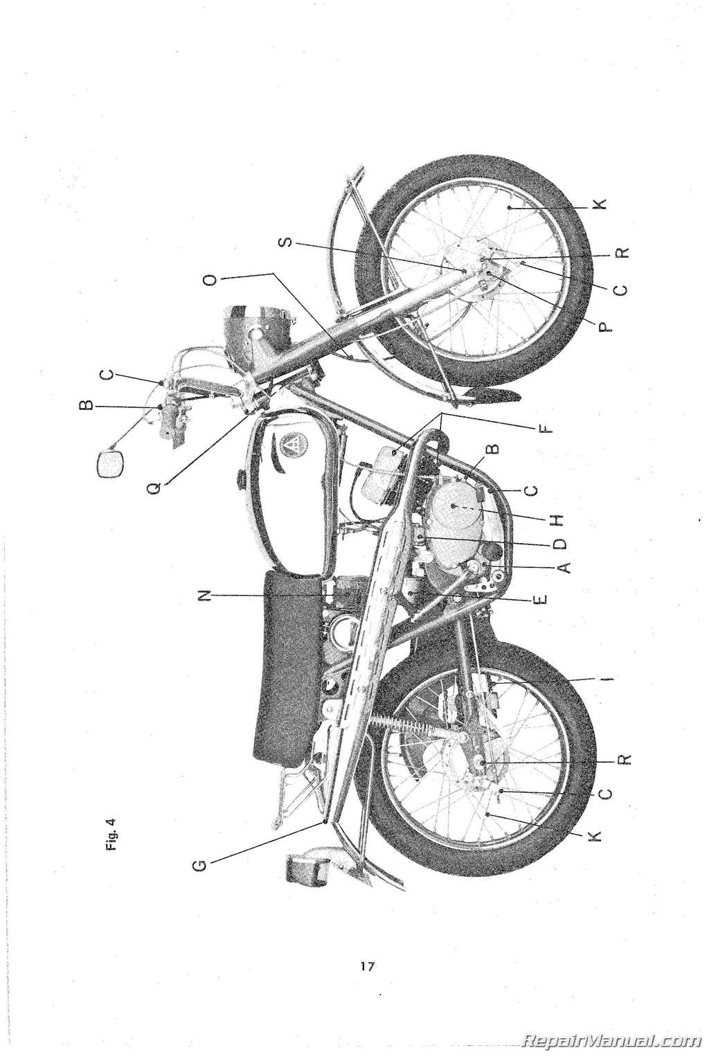
Side view of motorcycle
Front and rear brake components
Cable adjuster and brake lever details
Front brake cable slack adjustment
Rear brake adjustment
Stoplight switch
Loosening pinch bolt—front axle
Lubricating brake cam shaft
Rear axle assembly
Chain, chain guard and chain guide
Master link
Chain adjuster
Chain slack and chain guide clearance setting
Removing clip from master link
Measuring chain wear
Cross section of clutch assembly
Clutch lever free play
Clutch cable and lever details
Kickstarter lever hold-down technique
Transmission drain plug location
Removing clutch side cover
Removing clutch disc and spacers
Clutch holding tool in position
Clutch assembly
Pinion bushing position
Magneto/alternator components
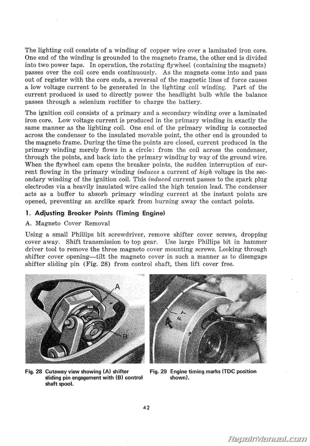
Shifter sliding pin engagement
Engine timing marks
Breaker gap setting
Magneto frame assembly
Removing flywheel nut
Using flywheel puller to remove flywheel
Flywheel details
Cylinder assembly
Removing cylinder
Removing piston pin snap rings
Withdrawing piston pin
Piston ring side clearance measurements
Piston to cylinder clearance
Squaring piston ring in cylinder
Measuring piston ring end gap
Piston ring end gap measurements
Installing piston onto connecting rod
Installing cylinder base gasket
Installing cylinder
Tightening cylinder head nuts
Magneto cover assembly
Crankcase assembly
Crankshaft assembly
Transmission and kick starter assembly
Shift mechanism details
Control shaft details
Cross section of transmission
Cross section of kick starter drive mechanism
Shifter cover opening
Shifter arm adjustment measurements
Transmission drain plug
Removing nut securing primary gear
Removing counter shaft sprocket nut
Removing shaft collar from counter shaft
Method of separating crankcase halves
Depressing control shaft spring stopper
Heating bearing bosses
Method of extracting mainshaft bushing
Crankcase oil passage and transmission breather
Crankshaft, measurements and clearances
Components assembled into right case
Applying sealer to crankcase
Installation pattern for crankcase screws
Installing kick spring
Headlight assembly
Electrical system components
Cross-section view of horn
Main switch positions
Hodaka ACE 90 wiring diagram
Method of ballasting trickle charger circuit
Selenium rectifier test
Spark plug details
Normal plug condition
Oil-fouled plug
Carbon-fouled plug
Overheated plug condition
Whiskered plug condition
Carburetor starting circuit
Carburetor idle to intermediate speed circuit
Carburetor intermediate to high speed circuit
Removing main jet
Throttle adjuster
Adjusting idle with air screw
Throttle valve cutaway
Jet needle
Float height measurement
Method of adjusting float height
A Fuel system components
Exhaust system
Details of frame, steering head bearing assembly, front fork assembly and handlebars
Loosening steering head nut
Adjusting steering head bearing play
Lubricating lower steering head bearing
Removing handlebar holder
Using “C” spanners to remove inside nut
Supporting fork assembly when removing or replacing
View showing ball bearings packed into bearing race
Front fork details
Measuring oil level in front fork
Dismantled fork assembly
Using tool to pull inner tube into position
Rear fork assembly
Method of releasing saddle cover clips
Stretching new cover over saddle
Brake pedal assembly
Footrest assembly
Battery bracket assembly
Side stand
Tool box assembly
Detail of A and B spokes
Installing first “A” spoke
Installing “A” spokes into rim
Installing second set of “A” spokes
Installing first “B” spoke
Installing final set of “B” spokes
ACE 90 port timing diagram
Shop tools


