Description
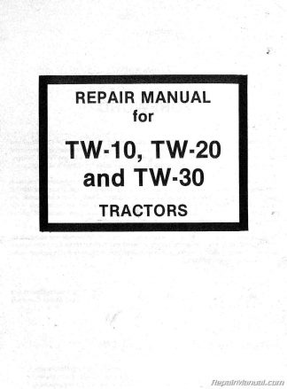
This Ford TW-10 TW-20 TW-30 Tractor Service Repair Manual includes 596 pages of repair information for the proper servicing of the Ford TW-10, TW-20 and TW-30 Tractors. The information is essential for all mechanics and will be especially meaningful to those who have attended the Training Programs for the TW-10, TW-20 and TW-30 Tractors. We recommend therefore, that this manual be readily available for reference at all times. The Ford TW-10 TW-20 TW-30 Tractor Service Repair Manual is grouped into parts, each containing chapter divisions. The chapters contain such information as general operating principles, detailed inspection and repair procedures, and full specifics regarding trouble shooting, specifications, and special tools. Whenever possible, the special tools are illustrated performing their specific operations. Any reference made in the manual to right, left, front, rear, top or bottom, is as viewed facing the direction of forward travel from the driver’s seat.
The engine described in this Ford TW-10 TW-20 TW-30 Tractor Service Repair Manual is a six cylinder diesel “in-line” type with direct fuel injection and overhead valve design. The displacement amounts to 401 cu. in. (6580 cc), the bore to 4.4 in. (111.76 mm) and the stroke to 4.4 in. (111.76 mm). Because of the bore and stroke dimensions it is referred to as a square engine.
Ford TW-10 TW-20 TW-30 Tractor Service Repair Manual Tractors Covered
Ford TW-10
Ford TW-20
Ford TW-30
Ford TW-10 TW-20 TW-30 Tractor Service Manual Table of Contents
PART 1 ENGINE SYSTEM
Chapter 1 – ENGINE AND LUBRICATION SYSTEM
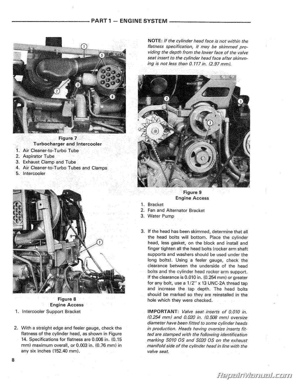
Description and Operation, Cylinder Head, Valves, and Related Parts, Engine Front Cover and Timing Gears, Oil Pan and Oil Pump, Connecting Rods, Bearings, Pistons, Rings, Cylinder Block and Sleeves, Main Bearings, Flywheel and Crankshaft, Camshaft, Engine Compression Test
Chapter 2 – TURBOCHARGER
Description and Operation, Turbocharger Overhaul, Trouble Shooting
Chapter 3 – INTERCOOLER
Description and Operation, Intercooler Overhaul, Heat Exchanger Service and Overhaul
Chapter 4 – COOLING SYSTEM
Description and Operation, Radiator and Thermostats, Water Pump
Chapter 5 – TROUBLE SHOOTING
Chapter 6 – SPECIFICATIONS AND SPECIAL TOOLS
PART 2 FUEL SYSTEM
Chapter 1 – FUEL SYSTEM – GENERAL
Description and Operation, Air Cleaner, Fuel Tank, Lines and Filter, Fuel Lift Pump, Adjustments, Bleeding the Fuel System
Chapter 2 – INJECTORS
Description and Operation, Overhaul
Chapter 3 – FUEL INJECTION PUMP
Description and Operation, Overhaul
Chapter 4 – TROUBLESHOOTING, SPECIFICATIONS AND TOOLS
Trouble Shooting, Specifications and Special Tools
PART 3 ELECTRICAL SYSTEM
Chapter 1 – WIRING, LIGHTS & INSTRUMENTS
Wiring Harnesses and Circuit, Description Fuses, Circuit Breakers, and Fuse Link Lights and Switches Instrument Cluster
Chapter 2 – BATTERY
Description, Specific Gravity, Maintenance, Removal and Installation Charging, Battery Tests
Chapter 3 – ALTERNATOR CHARGING SYSTEM
Introduction, Description and Operation, In-Vehicle Tests, In Vehicle Service Procedures, Alternator Overhaul and Bench Check
Chapter 4 – STARTING SYSTEM
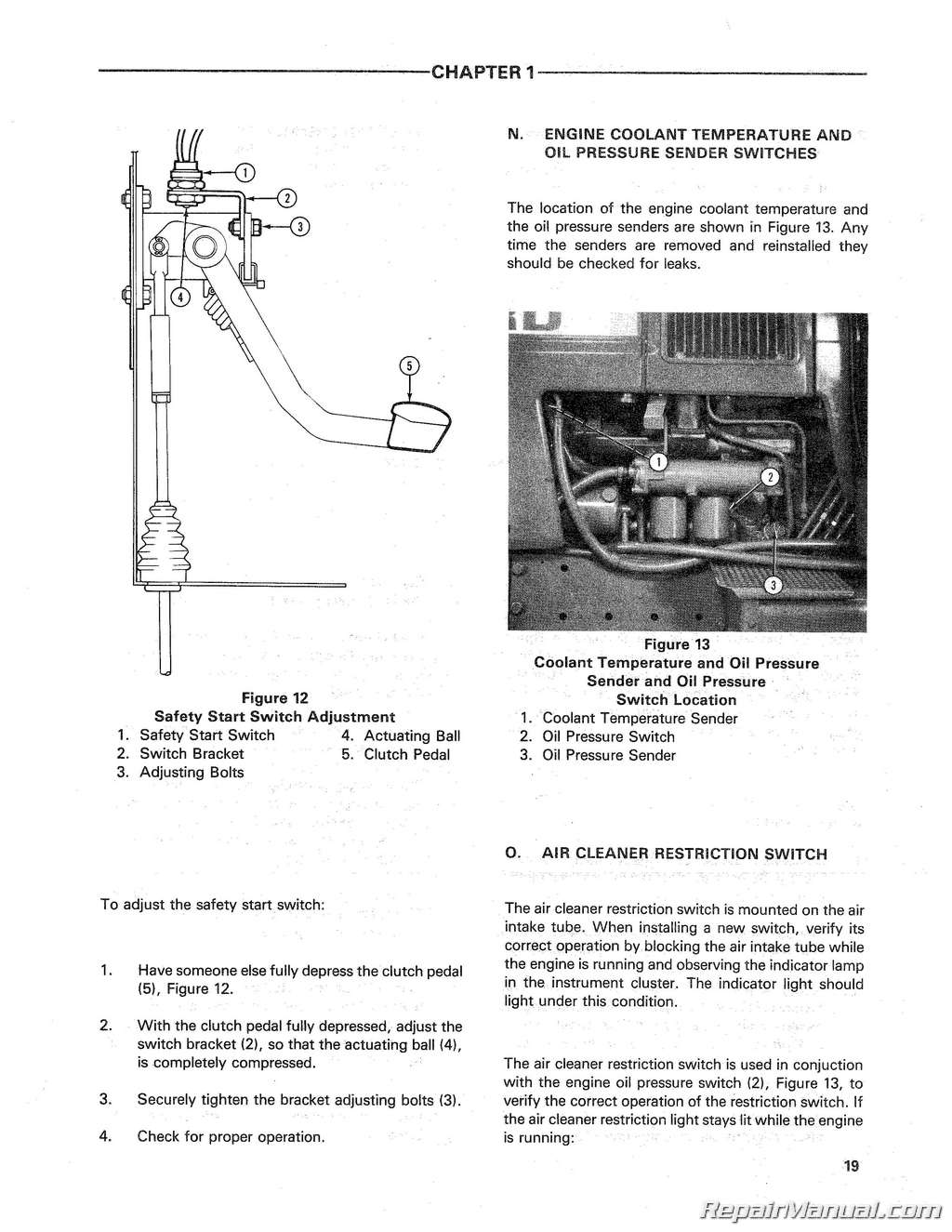
Description, Starting Motor Tests, Starting Motor Service, Safety Start Switch
Chapter 5 – CAB ELECTRICAL
General, Lights and Switches, Wiper/Washer System, Electric Controls
Chapter 6 – TROUBLESHOOTING SPECIFICATIONS & TOOLS
Trouble Shooting, Specifications, Tools
PART 4 TRANSMISSION AND CLUTCH
Chapter 1 – SERVICING THE TRANSMISSION
Introduction to Servicing the Transmission, Parking Brake Actuator, Rod and Linkage Adjustment, Gearshift Control Assembly, Gearshift Cover and Interlock Mechanism, Rear End Overhaul, Dual Power Planetary Gear Set Overhaul, Dual Power Control Valve Overhaul, Front End Overhaul, Complete Overhaul
Chapter 2 – THE CLUTCH AND RELATED COMPONENTS
Clutch Overhaul, Adjustments and Related Component Overhaul
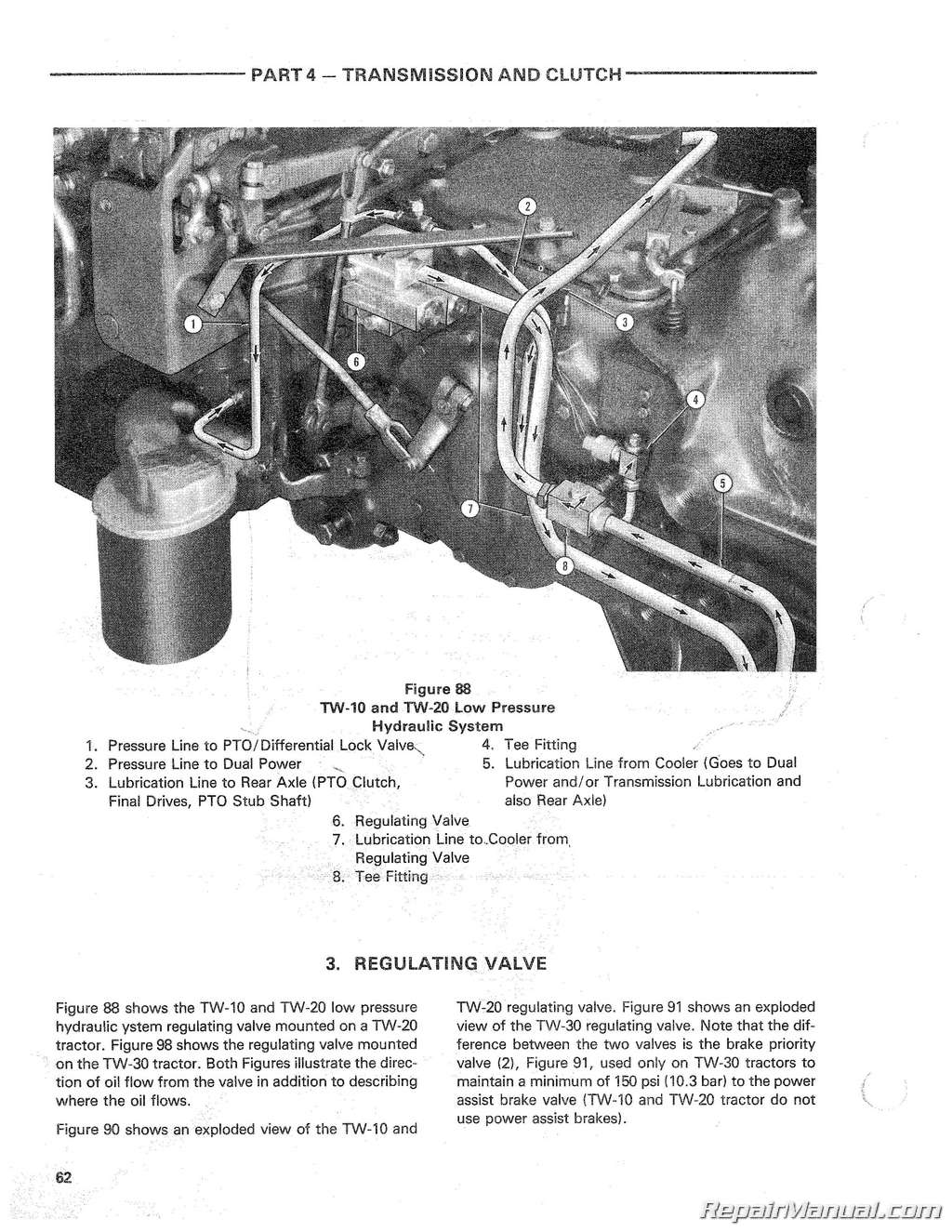
Chapter 3 – LOW PRESSURE HYDRAULIC SYSTEM
Introduction, Pump, Regulating Valve, Pressure Checks
Chapter 4 – TROUBLESHOOTING
Trouble Shooting, Reference Diagrams
Chapter 5 – SPECIFICATIONS AND SPECIAL TOOLS
PART 5 – REAR AXLE, BRAKES AND POWER TAKE-OFF
Chapter 1 – TROUBLESHOOTING, PRESSURE CHECKS, ADJUSTMENTS AND REFERENCE DIAGRAMS
Trouble Shooting, Pressure Checks, Adjustments, Reference Diagrams
Chapter 2 – SERVICING THE REAR AXLE AND BRAKES
Axle Shaft and Housing Overhaul, Planetary Gear Assembly Overhaul, Differential and Differential Lock Overhaul, Drive Pinion Overhaul, Brake Disc Overhaul, Brake Hydraulic System and Component Overhaul
PART 6 HYDRAULIC SYSTEM
Chapter 1 – HYDRAULIC SYSTEM AND REMOTE CONTROL VALVE OPERATION, AND PRESSURE CHECKS
Hydraulic System Operation, Draft and Position Control Operation, Remote Control Valve Operation, Pressure Checks
Chapter 2 – COMPONENT OVERHAUL
Hydraulic Lift Cover, Lift Cylinder and Control Valve Assembly, Lower Link Torsion Bar Linkage, Hydraulic Pump Cover and Valve Assembly, Hydraulic Pump, and Oil Inlet Filter, Remote Control Valves, Adjustments
Chapter 3 – TROUBLESHOOTING & SPECIFICATIONS
PART 7 STEERING SYSTEM, FRONT AXLE, WHEELS AND TIRES
Chapter 1 – STEERING SYSTEM
Description, Component Removal and Installation, Component Overhaul
Chapter 2 – FRONT AXLE
Toe-In Adjustment, Front Wheel Spindle and Bearing Overhaul, Front Axle Overhaul, Front Pedestal Overhaul, Front Axle Conversion
Chapter 3 – WHEELS AND TIRES
Front Wheel Adjustment, Rear Wheel Adjustment, Changing Tires
Chapter 4 – TROUBLE SHOOTING AND TESTING
Chapter 5 – SPECIFICATIONS AND SPECIAL TOOLS
PART 8 HEATING & AIR CONDITIONING
Chapter 1 – AIR CONDITIONING
Introduction, Compressor Clutch Assembly, Compressor Oil Level; Discharging, Evacuating and Charging System, Compressor Removal and Repair, Condenser/Oil Cooler, Dehydrator, Condenser Thermostat, Air Filter, Expansion Valve, Blower, Evaporator Core, Tubes and Hoses
Chapter 2 – HEATING
Introduction, Operation, Servicing, Maintenance
Chapter 3 – TROUBLESHOOTING AND WIRING DIAGRAM
Trouble Shooting, Torque Specifications, Wiring Diagram
Chapter 4 – SPECIFICATIONS AND SPECIAL TOOLS
PART 9 COMPONENT REMOVAL
Chapter 1 – REMOVING AND INSTALLING PROCEDURES
Removing and Installing the Cab, Removing and Installing the Engine, Removing and Installing the Flat Deck, Removing and Installing the Transmission, Removing and Installing the Rear Axle and Center Housing
Chapter 2 – SPECIAL TOOLS
PART 10 FRONT WHEEL DRIVE
Chapter 1 – FRONT WHEEL DRIVE TRANSFER BOX
Transfer Box – Description and Operation, Transfer Box – Overhaul
Chapter 2 – TRANSMISSION HANDBRAKE AND REDUCTION GEAR ASSEMBLY
Transmission Handbrake and Reduction Gear Assembly- Description and Operation, Transmission Handbrake and Reduction Gear Assembly- Overhaul
Chapter 3 – FRONT WHEEL DRIVE AXLE ASSEMBLY
Axle — Description and Operation, Axle — Overhaul
Chapter 4 – SPECIFICATIONS AND SPECIAL TOOLS

