Description
This Deutz-Allis 5220 5230 Diesel 2 and 4WD Synchro Factory Service Manual provides detailed service information, step-by-step repair instruction and maintenance specifications for Deutz-Allis 5220 and 5230 Diesel 2 and 4WD Synchro models. Please note this manual is a reproduction of the original, out of print manual.
Table of Contents
GENERAL SPECIFICATIONS
SAFETY PRECAUTIONS.
IMPORTANT SAFETY DECALS
ROLL OVER PROTECTIVE STRUCTURES .
TO OUR CUSTOMER
USER’S RESPONSIBILITY
TRACTOR IDENTIFICATION.
SERVICE PROCEDURES
METRIC COMPONENT INFORMATION.
LOCTITE PRODUCTS.
METRIC/U.S. CUSTOMARY UNIT EQUIVALENTS
TORQUE CHART
ENGINE
1.
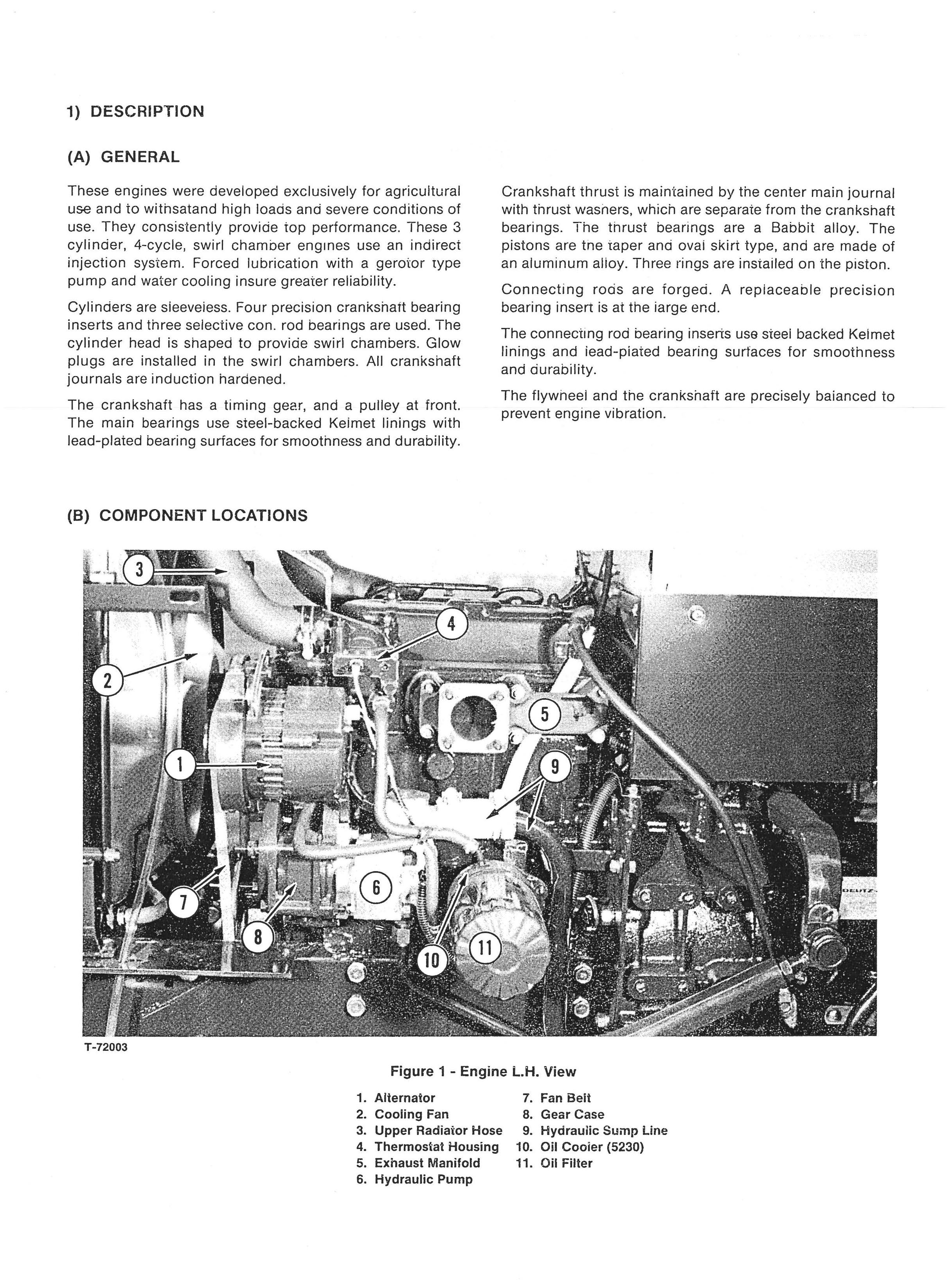
DESCRIPTION
A. General.
B. Component Location .
C. Performance Curve.
2. SPECIFICATIONS.
3. FITS AND TOLERANCES
4. ENGINE TORQUE SPECIFICATIONS
5. DISASSEMBLY
A. Cylinder Head
B. Fan and Water Pump
C. Injection Pump
D. Gear Cover and Gear Train
E. Flywheel
F. Oil Pump
G. Camshaft
H. Piston and Connecting Rod
I. Crankshaft
J. Cylinder Block
6. TECHNICAL GUIDE .
A. Injection Timing
B. Compression Check
7. TROUBLESHOOTING
FUEL INJECTION
CONSTRUCTION AND OPERATION FUEL INJECTION PUMP
CONSTRUCTION AND OPERATION NOZZLE .
FUEL INJECTION PUMP MODES .
HANDLING FUEL
FUEL INJECTION PUMP DISASSEMBLY .
ASSEMBLY
INSTALLATION
UNGLEICH UNIT ADJUSTMENT.
HANDLING OF NOZZLE AND HOLDER .
REPAIR
TROUBLESHOOTING
HYDRAULIC
General
Specifications.
Hydraulic Lift
3-Point Hitch Hydraulic System
Hitch and Controls.
Drawbar
3-Point Hitch.
Upper Link
Hitching To Implement.
Position Control Lever .
Draft Control Lever
Rate of Lower Control.
Remote Valve Lever
Draft Sensing Adjustment .
Pump Cutoff Adjustment
Feedback Lever Adjustment
Disassembly/Inspection and Assembly of Gear Pump (For Implement)
Gear Pump Removal.
Gear Pump Disassembly
Inspection and Repair.
Reassembly.
Pump Installation.
Hydraulic Control Valve
Raise Position
Neutral Position
Lower Position .
Valve Components
Hydraulic Cylinder Housing.
Removal
Disassembly
Flow Control Valve and Housing Cover Removal and Disassembly
Assembly of Flow Control .
Piston Removal
Lift Arm and Hydraulic Arm Removal .
Inspection .
Control Valve
Control Valve Disassembly
Control Valve Inspection .
Control Valve Reassembly
Cover Assembly
Valve Specifications
Dissassembly of Cover Assembly
Cleaning and Checking
Reassembly
Relief Valve Setting .
Hydraulic Cylinder Reassembly and Adjustments
Hydraulic Cylinder Reassembly.
Hydraulic Lift Arm Adjustment.
Control Valve Linkage Installation
Control Valve and Control Link Adjustment
Upper Link Adjustments.
Pivot Bolt
Sensor Spring Bolt
Feedback Lever
Torque Chart.
Hydraulic Cylinder Trouble Shooting
Hydraulic Manifold Kit
Installation Instructions.
Spool Valve Kit
Mounting of Valve Assembly
Coupler Repair
Valve Repair
Testing Hydraulic Pump-With Remotes
Testing Hydraulic Pump-Without Remotes.
Tools For Hydraulic System
Flow Chart.
POWER STEERING (Optional)
I. SPECIFICATIONS.
II. SYSTEM DIAGRAM
III. CONSTRUCTION AND OPERATION
A. Construction .
B. Control Valve Operations
C. Parts Nomenclature
IV. MAINTENANCE AND
PERIODIC INSPECTION.
V. TROUBLE SHOOTING.
VI. OVER HAUL.
A. Tools.
B. Remove The Power Steering.
C. Disassembly.
VII. CLEANING AND INSPECTION
A. Cleaning
B. Specified Wear Limits
VIII. REASSEMBLY
A. Box.
B. Rod.
C. Valve
D. Shifter.
E. Install Valve to Shifter .
F. Install Valve & Shifter to Cylinder.
G. Install Cylinder/Valve Assy, on Tractor
H. Restart System
IX. POWER STEERING PUMP.
X. INSTRUCTION SHEET FOR FIELD
INSTALLING POWER STEERING KIT .
POWER TRAIN
SPECIFICATIONS.
TRACTOR SEPARATION
DISASSEMBLY SEQUENCE.
CLUTCH
CLUTCH CONTROL.
PTO DRIVE SHAFT
PTO SHAFT LOWER .
TRANSMISSION.
TRANS COUNTER SHAFT
REVERSE IDLER
RANGE SHIFT CONTROLS.
SUB GEAR SHAFT.
TRANS MAIN SHAFT.
PTO CONNECTING SHAFT.
REAR MAIN HOUSING
DRIVE PINION SHAFT.
PTO COUNTERSHAFT.
PTO EXTENSION SHAFT
BRAKES.
REAR AXLE SLEEVES
DIFFERENTIAL.
RING GEAR AND PINION ADJUSTMENT
DIFFERENTIAL LOCK LINKAGE .
FWD IDLER AND DRIVE SHAFT
POWERTRAIN CHART (2WD).
POWERTRAIN CHART (FWA).
FWA FRONT AXLE
General Information .
Removing The Front Axle .
Replacing The Front Axle
Front Axle Disassembly.
Front Wheel Removal
Front Axle Oil.
Front Gear Case Disassembly .
Front Axle Disassembly.
Differential Carrier Disassembly.
Front Axle Inspection, Adjustment and Assembly .
Assembly of Differential Carrier and Bevel Pinion
Assembly of Front Axle
Front Axle Specifications
Special Tools .
Front Axle Torques.
ELECTRICAL .
Wiring Diagram .
Instruments and Controls .
Tachometer.
Light Switch.
Glow Lamp
Front PTO Switch
Key Switch
Temperature Gauge
Indicator Light Cluster
Fuse Box.
Flasher Unit.
Safety Start Switches
Front PTO Switch Installation
Battery.
Starter.
Introduction and Features
Specifications and Performance
Construction and Function
Operation
Adjustment.
Installation.
Disassembly
Reassembling.
Inspection and Maintenance .
Maintenance Standards
Performance Test
Trouble Shooting and Remedy.
Alternator With 1C Regulator
Features.
Construction.
Wiring Diagram
1C Regulator Working Principle .
Handling Precautions.
Disassembly
Inspection and Servicing.
Reassembling.
Performance Test
Trouble Shooting .
Specification
CHASSIS .
Steering Section.
Instruction Sheets .


