Description
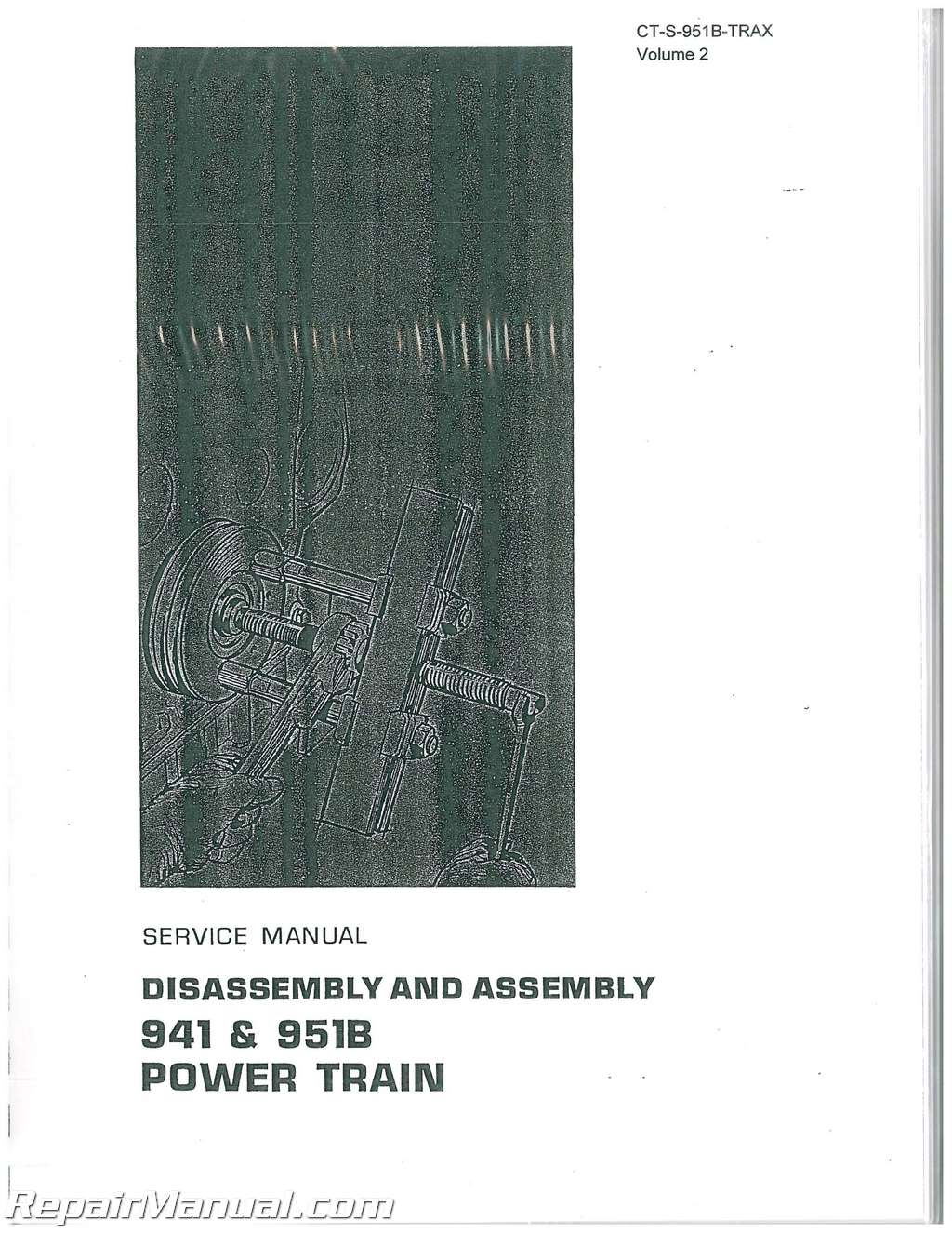
This two volume, 658 page, Caterpillar 951B Traxcavator Service Manual provides detailed service information, step-by-step repair instruction and maintenance specifications for Caterpillar 951B Traxcavators
This Caterpillar 951B Traxcavator Service Manual covers the following tractors:
Traxcavator #951B (32F)
Traxcavator #951B (69H1 & up) (79H1 & up) (86J1 & up)
Caterpillar 951B Traxcavator Service Manual Table of Contents
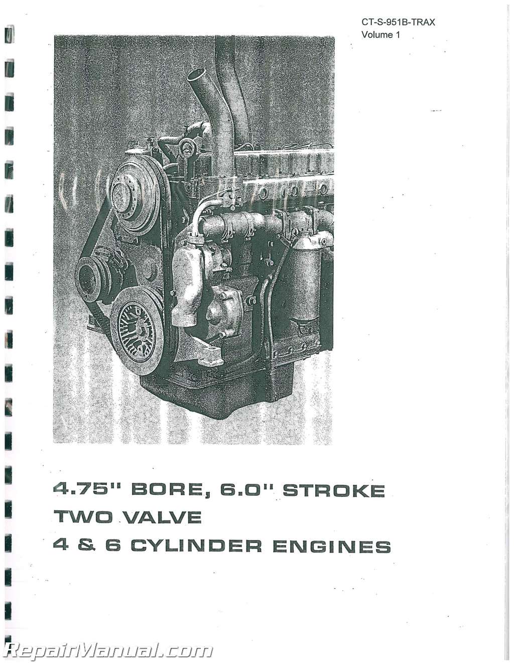
4.75″ BORE, 60″ STROKE TWO VALVE 4 & 6 CYLINDER ENGINE Manual
FUEL SYSTEM TESTING AND ADJUSTING
ADDITIONAL TOOL REQUIREMENTS
ILLUSTRATED SPECIFICATIONS
4.75 BORE, FOUR CYLINDER, TWO VALVE VEHICLE ENGINE Manual
Systems Operation – Air Induction and Exhaust Systems
Alternators
Circuit Breaker
Cooling System
Fuel Injection Pump Operation
Fuel Injection Valve
Fuel System
Generator
Generator Regulator
Governor Operation
Lubrication System
Solenoid
Starting Motor
Starting and Charging Systems
Valves and Valve Mechanism
Testing and Adjusting – Air Induction and Exhaust System
Checking Inlet Manifold Pressure at Torque
Converter Stall Speed
Compression
Crankcase Pressure
Cylinder Condition
Cylinder Head
Measuring Inlet Manifold Pressure
Precombustion Chamber Position
Restriction of Air Inlet and Exhaust
Valve Clearance Setting
Basic Block
Connecting Rods and Pistons
Crankshaft
Cylinder Liner Projection
Flywheel
Oil Pump Installation
Cooling System
Testing Cooling System
Visual Inspection
Flexible Drive Coupling
Fuel System
Accessory Drive Shaft Timing
Check Fuel Injection Pump Lifter
Washer and Pump Plunger
Checking Fuel Injection Pump Timing—On Engine
Checking Fuel Injection Valve
Fuel Bypass Valve
Fuel Injection Pump Timing Dimension Setting-Off Engine
Fuel Injection Service
Fuel Injection Valve
Fuel Injection Pump Installation
Fuel Rack Setting
Fuel System Adjustments
Governor Adjustments
Locating Top Center Position for number 1 Piston
Testing Fuel Injection Equipment
Visual Inspection
Lubrication System
Excessive Oil Consumption
High Oil Pressure
Low Oil Pressure
Oil Pressure
Unusual Bearing Wear
Problem Solving
Starting and Charging System
Battery
Charging System
Starting System
Specifications
Alternators
Alternator Regulator
Connecting Rod
Crankshaft
Cylinder Block
Cylinder Head
Cylinder Liner
Flexible Drive Coupling
Fuel Bypass Valve
Fuel Injection Equipment
Fuel Transfer Pump
Generators
Generator Regulators
Governor
Oil Filter
Oil Pump
Piston and Rings
Power Take-off and Hydraulic Pump Drive
Radiator
Starter Solenoids
Starting Motors
Temperature Regulator
Timing Gears
Turbocharger (AiResearch-T0490)
Turbocharger (AiResearch-T1210)
Turbocharger (Schwitzer E Model)
Turbocharger (Schwitzer-3LK)
Valves
Valve Cover
Valve Rocker Arms and Lifters
Water Pump
HOW TO USE THE 951B TRAXCAVATOR SERVICE MANUAL
The Service Manual is divided into five parts. Although all are related, each part can be used to fulfill a specific need. Use of one part or the complete manual will depend on the problem facing the serviceman, his knowledge of the machine and its service procedure.
PART I is Lubrication and Maintenance Information. In it is the booklet which was also included with the machine. It is provided with the manual as a source of information concerning types of lubricant, capacities and adjustment procedures.
PART II is Systems Operation which includes a thorough discussion of the way each system in the machine works. This is divided into four sections: Engine, Power Train, Chassis and Loader Portion. These sections have a further breakdown designated by a number in the upper right corner of each page. This number provides a means of identifying a page, should a revised or new page insertion become necessary. The number also serves as a page location for listing in the Table of Contents.
PART III, Testing and Adjusting, includes information necessary to troubleshoot a particular system within the machine. This is sectionalized in the same manner as Systems Operation.
PART IV, pictorially disassembles and assembles machine components. A Service Guide in each section illustrates, in chart form, the steps necessary to remove a component not immediately accessible. Numbers are used on some illustrations to indicate the sequence of disassembly If the disassembly or assembly sequence is obvious, the numbers are omitted. A circled number on an illustration, with or without a prescribed sequence, indicates that a specific procedure is necessary to disassemble or assemble The information will appear adjacent to or on the page opposite the illustration. Adjustment procedures which are required at assembly time; ie, bearing clearance, bearing
preloads, are shown in the Disassembly and Assembly part. If however, an adjustment procedure is part of a maintenance or troubleshooting function the symbol for adjustment will be used. The adjustment procedures will be given in the Lubrication and Maintenance Information or Testing and Adjusting part. General Instructions, a review of many items which a mechanic encounters in servicing machines, are included in the Disassembly and Assembly part Proper installation of lip-type seals, Duo-Cone floating seals and locks are examples. These items are covered in topic form so a specific subject can be located quickly.
PART V, Specifications, is an illustrated listing of tolerances of new parts, pressures, adjustments, torque values, etc Maximum and Minimum tolerances are listed in some instances. These are reasonable figures to use in determining when to replace parts.
More information available upon request…


