Description
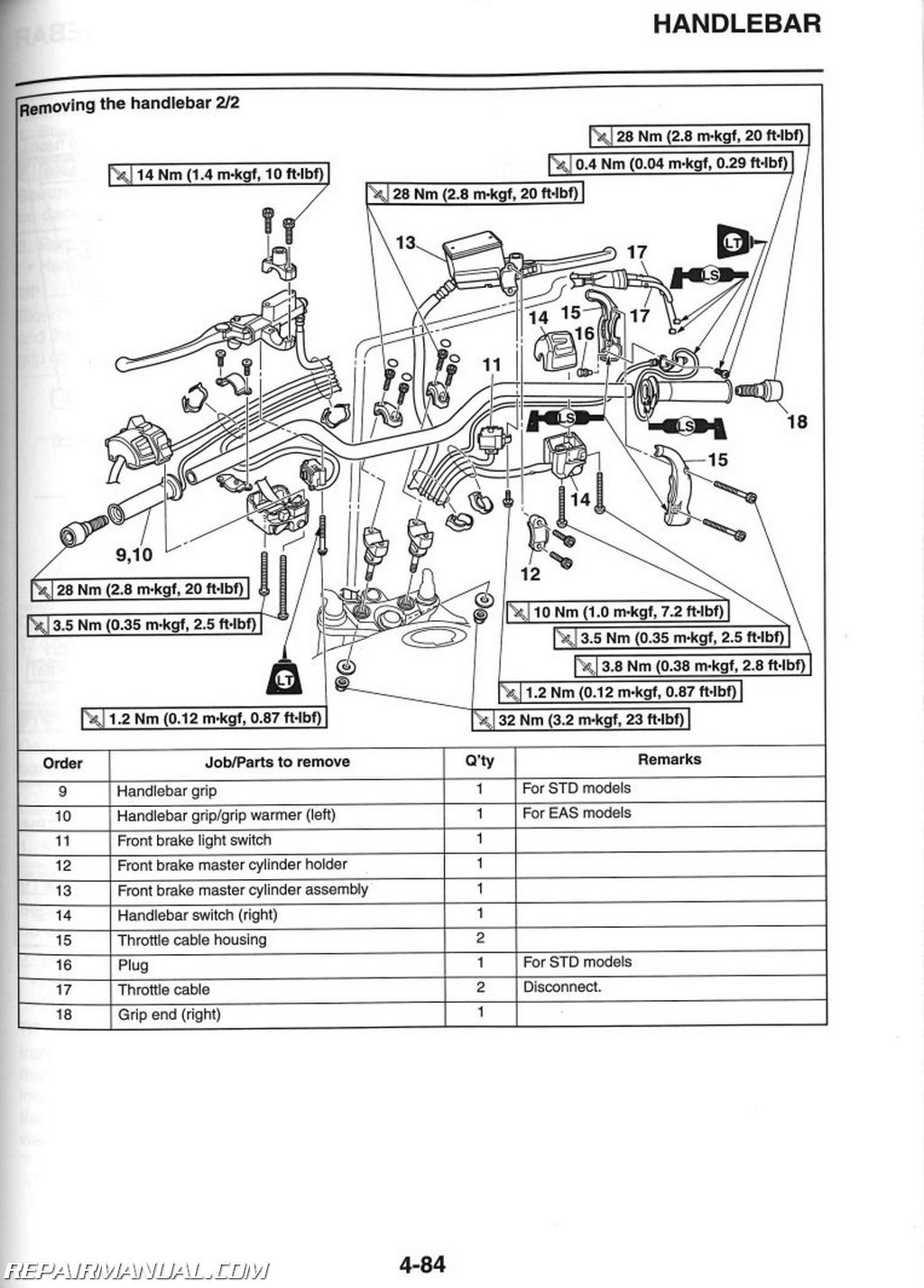
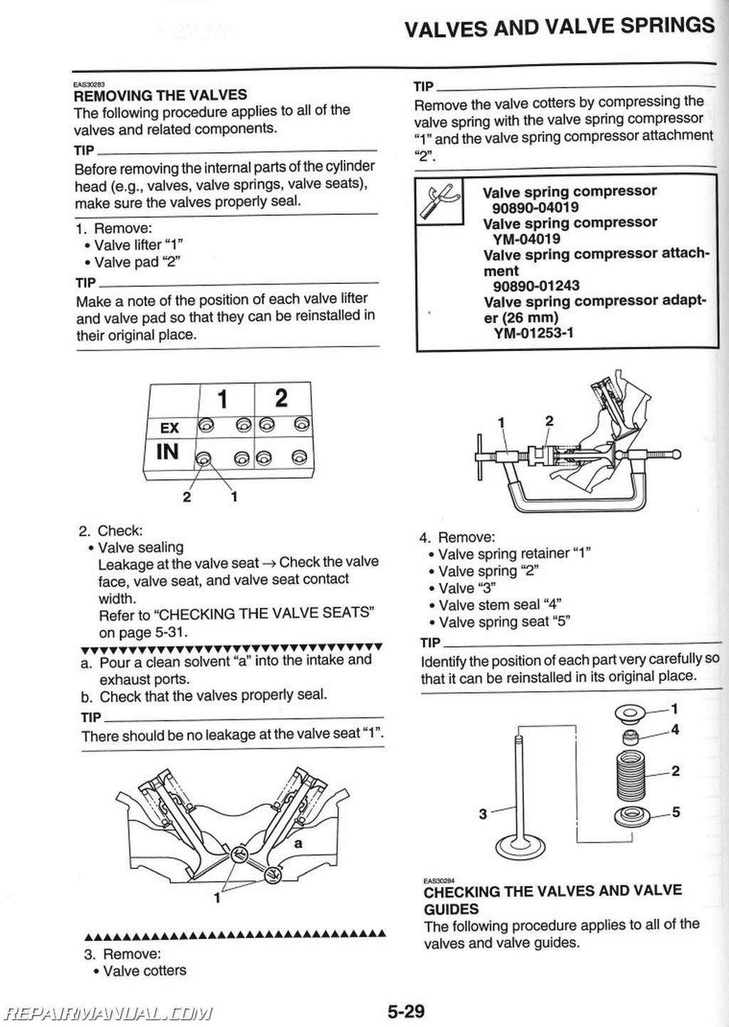
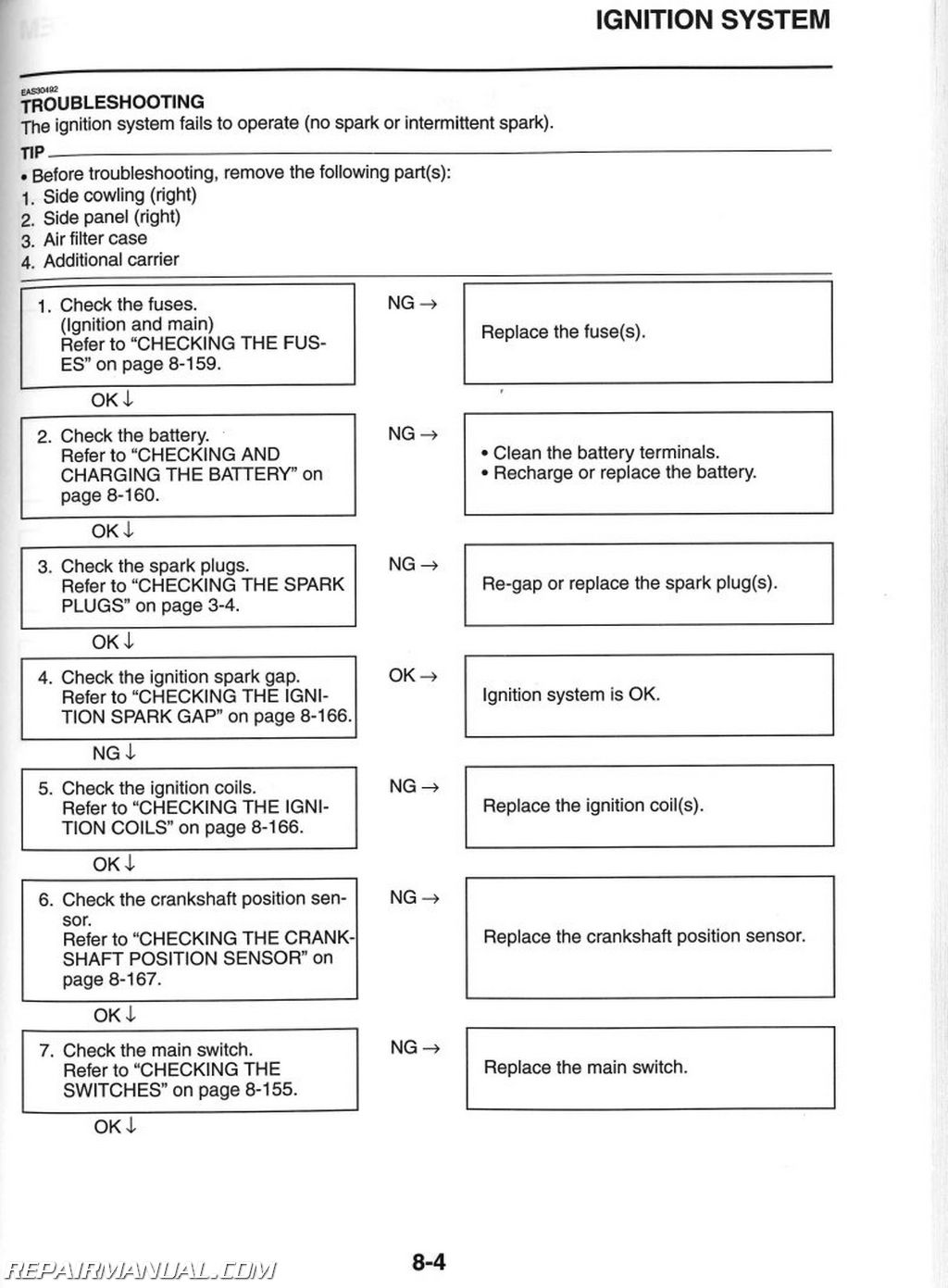
This 2014-2021 Yamaha XTZ1200E Super Tenere Factory Service Manual provides detailed service information, step-by-step repair instruction and maintenance specifications for:
2014 2015 2016 2017 2018 2019 2020 2021 Yamaha XTZ12 Super Tenere motorcycles
The Yamaha Super Tenere is a very reliable adventure bike which makes it easily to neglect basic maintenance. Get the official Yamaha manual and take the time to study the maintenance items and actually perform them and your ownership experience and longevity of your motorcycle will be greatly increased.
Table of Contents
General Information
Specifications
Periodic Checks And Adjustments
Chassis
Engine
Cooling System
Fuel System
Electrical System
Troubleshooting
Index of Topics
Chapter 1: General Information
Identification
Vehicle Identification Number
Model Label
Features
Outline Of The Fi System
FI System
YCC-T (yamaha Chip Controlled Throttle)
Outline Of The Cruise Control System
Outline Of The Ubs
Outline Of The Abs
Abs Component Functions
Ubs And Abs Operation
Abs Self-diagnosis Function
Abs And Ubs Function
Outline Of The Tcs (traction Control System)
Multi-function Meter Unit
D-mode (drive Mode)
Important Information
Preparation For Removal And Disassembly
Replacement Parts
Gaskets, Oil Seals And O-rings
Lock Washers/plates And Cotter Pins
Bearings And Oil Seals
Circlips
Rubber Parts
Basic Service Information
Quick Fasteners
Electrical System
Special Tools
Chapter 2: Specifications
General Specifications
Engine Specifications
Chassis Specifications
Electrical Specifications
Tightening Torques
General Tightening Torque Specifications
Engine Tightening Torques
Chassis Tightening Torques
Lubrication Points And Lubricant Types
Engine
Chassis
Lubrication System Chart And Diagrams
Engine Oil Lubrication Chart
Lubrication Diagrams
Cooling System Diagrams
Cable Routing
Chapter 3: Periodic Checks And Adjustments
Periodic Maintenance
Introduction
Periodic Maintenance Chart For The Emission
Control System
General Maintenance And Lubrication Chart
Checking The Fuel Line
Checking The Spark Plugs
Adjusting The Valve Clearance
Checking The Engine Idling Speed
Synchronizing The Throttle Bodies
Checking The Exhaust System
Checking The Cylinder Head Breather Hose
Checking The Canister (for California Only)
Replacing The Air Filter Element
Adjusting The Clutch Lever
Checking The Clutch Fluid Level
Bleeding The Hydraulic Clutch System
Adjusting The Front Disc Brake
Checking The Brake Fluid Level
Bleeding The Hydraulic Brake System (abs)
Checking The Front Brake Pads
Checking The Rear Brake Pads
Checking The Brake Hoses
Checking The Wheels
Checking And Tightening The Spokes
Checking The Tires
Checking The Wheel Bearings
Checking The Swingarm Pivot
Lubricating The Swingarm Pivot
Checking And Adjusting The Steering Head
Lubricating The Steering Head
Checking The Fasteners
Lubricating The Levers
Lubricating The Pedals
Checking The Sidestand
Checking The Centerstand
Lubricating The Sidestand
Lubricating The Centerstand
Checking The Sidestand Switch
Checking The Front Fork
Adjusting The Front Fork Legs (for Std Models)
Adjusting The Damping Force Of The Front Fork Legs
And Rear Shock Absorber Assembly (for Eas Models)
Checking The Rear Suspension
Adjusting The Rear Shock Absorber Assembly
(for Std Models)
Adjusting The Preload Of The Rear Shock Absorber
Assembly (for Eas Models)
Checking The Engine Oil Level
Changing The Engine Oil
Measuring The Engine Oil Pressure
Checking The Coolant Level
Checking The Coolant System
Changing The Coolant
Checking The Final Gear Oil Level
Changing The Final Gear Oil
Checking The Brake Light Switches
Adjusting The Rear Brake Light Switch
Checking And Lubricating The Cables
Checking The Throttle Grip Operation
Checking The Switches, Lights And Signals
Adjusting The Headlight Beams
Replacing The Headlight Bulbs
Replacing The Auxiliary Light Bulbs
Chapter 4: Chassis
General Chassis (1)
Installing The Seats
Installing The Carriers
General Chassis (2)
Removing The Abs Unit Cover (for Std Models)
Removing The Abs Unit Cover (for Eas Models)
Installing The Abs Unit Cover (for Std Models)
Installing The Abs Unit Cover (for Eas Models)
General Chassis (3)
Removing The Side Cowlings
Installing The Side Cowlings
Removing The Rear Side Cover (for Eas Models)
Installing The Rubber Dampers (for Eas Models)
Installing The Rear Side Cover (for Eas Models)
General Chassis (4)
Installing The Electrical Components Tray
General Chassis (5)
Assembling The Headlight
Instaling The Headlight Assembly
Adjusting The Windshield Height
General Chassis (6)
Removing The Air Filter Case
Front Wheel
Removing The Front Wheel
Disassembling The Front Wheel
Checking The Front Wheel
Maintenance Of The Front Wheel Sensor And
Sensor Rotor
Assembling The Front Wheel
Adjusting The Front Wheel Static Balance
Installing The Front Wheel (front Brake Discs)
Chapter 5: Engine
Engine Inspection
Measure The Compression Pressure
Engine Removal
Removing The Engine
Installing The Engine
Installing The Exhaust Pipe And Muffler
Camshafts
Removing The Cylinder Head Cover
Removing The Camshafts
Checking The Camshafts
Checking The Camshaft Sprocket
Checking The Timing Chain Tensioners
Checking The Decompression System
Installing The Camshafts
Installing The Cylinder Head Cover
Cylinder Head
Removing The Cylinder Head
Checking The Timing Chain Guide (exhaust Side)
Checking The Cylinder Head
Installing The Cylinder Head
Valves And Valve Springs
Removing The Valves
Checking The Valves And Valve Guides
Checking The Valve Seats
Checking The Valve Springs
Checking The Valve Lifters
Installing The Valves
Cylinder And Pistons
Removing The Pistons
Checking The Cylinders And Pistons
Checking The Piston Rings
Checking The Piston Pins
Installing The Pistons And Cylinder
Generator And Starter Clutch
Removing The Generator
Removing The Starter Clutch
Checking The Starter Clutch
Checking The Torque Limiter
Installing The Starter Clutch
Installing The Generator
Electric Starter
Checking The Starter Motor
Assembling The Starter Motor
Clutch
Removing The Clutch
Checking The Friction Plates
Checking The Clutch Plates
Checking The Clutch Spring Plate
Checking The Clutch Housing
Checking The Clutch Boss
Checking The Pressure Plate
Checking The Clutch Push Rods
Checking The Primary Driven Gear
Installing The Clutch
Disassembling The Clutch Master Cylinder
Checking The Clutch Master Cylinder
Assembling The Clutch Master Cylinder
Installing The Clutch Master Cylinder
Removing The Clutch Release Cylinder
Assembling The Clutch Release Cylinder
Installing The Clutch Release Cylinder
Pickup Rotor
Removing The Pickup Rotor
Installing The Pickup Rotor
Shift Shaft
Checking The Shift Shaft
Checking The Stopper Lever
Installing The Shift Shaft
Adjusting The Shift Pedal
Oil Pump
Removing The Oil Pan And Oil Strainer Cover
Checking The Oil Pump
Checking The Relief Valve
Checking The Oil Pipe
Checking The Oil Strainer
Assembling The Oil Pump
Installing The Oil Pan
Installing The Oil Strainer Cover
Crankcase
Removing The Rear Balancer
Disassembling The Crankcase
Checking The Crankcase
Checking The Rear Balancer
Checking The Timing Chain And Timing Chain Guide (intake Side)
Checking The Oil Nozzles
Assembling The Crankcase
Installing The Rear Balancer
Crankshaft And Balancer
Removing The Front Balancer Shaft
Removing The Balancer Shaft Journal Bearings
Removing The Crankshaft Journal Bearings
Removing The Connecting Rods
Checking The Crankshaft
Checking The Connecting Rods
Checking The Front Balancer
Installing The Connecting Rods
Installing The Crankshaft
Installing The Front Balancer Shaft
Transmission
Removing The Transmission
Checking The Shift Forks
Checking The Shift Drum Assembly
Checking The Transmission
Assembling The Main Axle And Drive Axle
Installing The Transmission
Middle Gear
Removing The Middle Driven Pinion Gear Assembly
Disassembling The Middle Driven Pinion Gear
Assembly
Removing The Middle Drive Pinion Gear Assembly
Disassembling The Middle Drive Pinion Gear
Assembly
Checking The Middle Driven Pinion Gear Assembly
Checking The Middle Drive Pinion Gear Assembly
Assembling The Middle Drive Pinion Gear Assembly
Installing The Middle Drive Pinion Gear Assembly
Assembling The Middle Driven Pinion Gear
Assembly
Installing The Middle Driven Pinion Gear Assembly
Measuring The Middle Gear Backlash
Adjusting The Middle Gear Backlash
Aligning The Middle Gear
Chapter 6: Cooling System
Radiator
Checking The Radiator
Installing The Radiator
Thermostat
Checking The Thermostat
Installing The Thermostat
Water Pump
Disassembling The Water Pump
Checking The Water Pump
Assembling The Water Pump
Installing The Water Pump
Chapter 7: Fuel System
Fuel Tank
Removing The Fuel Tank
Removing The Fuel Pump
Checking The Fuel Pump Body
Checking The Rollover Valve (for California Only)
Installing The Fuel Pump
Installing The Fuel Tank
Throttle Bodies
Checking The Injectors (before Removing)
Removing The Injectors
Checking The Injectors
Checking And Cleaning The Throttle Bodies
Checking The Throttle Body Joints
Installing The Injectors
Checking The Injector Pressure
Checking The Fuel Pressure
Adjusting The Throttle Position Sensor
Adjusting The Accelerator Position Sensor
Installing The Throttle Body Joints
Chapter 8: Electrical System
Ignition System
Circuit Diagram
Engine Stopping Due To Sidestand Operation
Troubleshooting
Electric Starting System
Circuit Diagram
Starting Circuit Cut-off System Operation
Troubleshooting
Charging System
Circuit Diagram
Troubleshooting
Lighting System
Circuit Diagram
Troubleshooting
Signaling System
Circuit Diagram
Troubleshooting
Cooling System
Circuit Diagram
Chapter 9: Troubleshooting
Fuel Injection System
Circuit Diagram
Ecu Self-diagnostic Function
Troubleshooting Method (ecu)
Diagnostic Mode (ecu)
Yamaha Diagnostic Tool
Troubleshooting Details (ecu)
Cruise Control System
Circuit Diagram
Cruise Control Circuit Operation
Basic Instructions For Troubleshooting
Basic Process For Troubleshooting
[a] Checking The Cruise Control System
Indicator Light
[b-1] Diagnosis Using The Fault Codes
[b-2] Diagnosis Using The Malfunction History
Codes
[b-3] Malfunction History Is Displayed
[b-4] Malfunction History Is Not Displayed
[c-1] Deleting The Fault Codes
[c-2] Final Check
Fuel Pump System
Circuit Diagram
Troubleshooting
Abs (anti-lock Brake System)
Circuit Diagram
Abs Components Chart
Abs Coupler Location Chart
Maintenance Of The Abs Ecu
Abs Troubleshooting Outline
Basic Instructions For Troubleshooting
Basic Process For Troubleshooting
[a] Checking The Abs Warning Light
[a-1] Only The Abs Warning Light Fails To Come On
[a-2] All Indicator Lights Fail To Come On
[a-3] The Abs Warning Light Flashes
[a-4] The Abs Warning Light Comes On
[b-1] A Fault Code Number Is Not Indicated By The Abs
Warning Light, But The Abs Warning Light Is On
[b-2] The Abs Warning Light Remains On
[b-3] Diagnosis Using The Fault Codes
[c-1] Deleting The Fault Codes
[c-2] Delete Function Test
[c-3] Final Check
Grip Warmer System (for Eas Models)
Circuit Diagram
Troubleshooting
Electronically Adjustable Suspension System
Circuit Diagram
Maintenance Of The Scu (suspension Control Unit)
Scu (suspension Control Unit) Self-diagnostic Function
Troubleshooting Method (scu)
Basic Instructions For Diagnostic Function
Troubleshooting Details (scu)
Electrical Components
Checking The Switches
Checking The Bulbs And Bulb Sockets
Checking The Fuses
Replacing The Ecu (engine Control Unit)
Checking And Charging The Battery
Checking The Relays
Checking The Relay Unit (diode)
Checking The Ignition Coils
Checking The Ignition Spark Gap
Checking The Crankshaft Position Sensor
Checking The Lean Angle Sensor
Checking The Starter Motor Operation
Checking The Stator Coil
Checking The Rectifier/regulator
Checking The Oil Level Switch
Checking The Fuel Sender
Checking The Fuel Meter/fuel Level Warning Light
Checking The Oil Level Warning Light
Checking The Radiator Fan Motor
Checking The Coolant Temperature Sensor
Checking The Throttle Position Sensor
Checking The Accelerator Position Sensor
Checking The Intake Air Pressure Sensor
Checking The Intake Air Temperature Sensor
Checking The Fuel Injectors
Checking The Throttle Servo Motor
Checking The Grip Warmers (for Eas Models)
Troubleshooting
Troubleshooting
General Information
Starting Failure
Incorrect Engine Idling Speed
Poor Medium-and-high-speed Performance
Faulty Gear Shifting
Shift Pedal Does Not Move
Jumps Out Of Gear
Faulty Clutch Performance
Overheating
Overcooling
Poor Braking Performance
Faulty Front Fork Legs
Unstable Handling
Faulty Lighting Or Signaling System
Self-diagnostic Function And Diagnostic Code Table (ecu)
Self-diagnostic Function Table
Communication Error With The Meter
Diagnostic Code: Sensor Operation Table
Diagnostic Code: Actuator Operation Table
Self-diagnostic Function And Diagnostic Code Table (scu) (for Eas Models)
Self-diagnostic Function Table
Diagnostic Code Table
Event Code Table


