Description
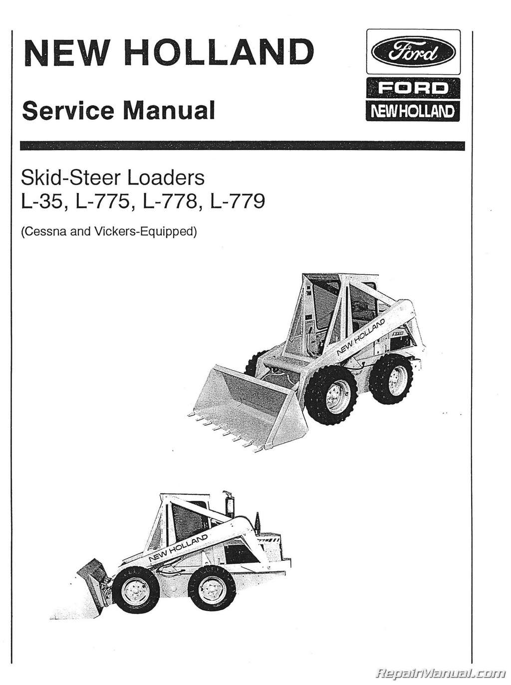
This 214 page, Ford New Holland L35 L775 L778 And L779 Skid Steer Service Manual is a reproduction of the original out of print manual. This book provides in condensed form, service and maintenance information which will serve to guide a serviceman when repairing or rebuilding Sperry New Holland L-35, L-775, L-778 or L-779 skid-steer loaders in the shop and to help him when diagnosing and correcting service difficulties in the field. The operator’s manuals and assembly information provided with each machine should be used in conjunction with this manual, as much of the information contained in this manual Is condensed or supplementary in nature. For instructions on engine repair, refer to the manufacturer’s repair manual.
Ford New Holland L35 L775 L778 And L779 Skid Steer Service Manual Model Coverage
Sperry New Holland L-35 skid-steer loaders
Sperry New Holland L-775 skid-steer loaders
Sperry New Holland L-778 skid-steer loaders
Sperry New Holland L-779 skid-steer loaders
Table of Contents
Foreword
Safety
Introduction
Servicing Vickers-equipped Loaders
Section 1 – Vickers Transmission Removal
Section 2 – Hydrostatic Transmission Operation
Section 3 – Vickers Transmission Disassembly
Section 4 – Vickers Transmission Pump And Motor Shimming
Section 5 – Shimming Procedure For Vickers Four-way Gear Box
Section 6 – Vickers Steering Control Adjustments
Section 7 – Vickers Vane Pump Removal, Inspection And Installation
Section 8 – Proportional Flow Divider
Section 9 – Steering Cylinder Rebuilding
Servicing Cessna-equipped Loaders
General Information
Section 1 – Cessna Transmission Removal
Section 2 – Cessna Transmission Overhaul
Section 3 – Cessna Transmission Oil Leaks
Section 4 – Shimming Four-way Gear Box
Section 5 – System Cleaning Procedure After Transmission Overhaul
Section 6 – Hydraulic Reservoir And Check Valve Assembly
Section 7 – Steering Neutralizer Repair
Section 8 – Cessna Steering Control Adjustments
Section 9- Cessna Gear Pump Removal, Inspection And Installation
General Information Vickers And Cessna-equipped Skid-steer Loaders
Section 1 – Start-up Procedure
Section 2 – Final Drive Disassembly And Assembly
Section 3 – Hydraulic System Pressure Checks
Section 4 – Servicing The Control Valve
Section 5 – Rebuilding Bucket And Boom Cylinders
Section 6-electrical System
Section 7- Boom Lockout
Section 8 – Fuel Tank Removal
Section 9 – Specifications – L-35 Loader, L-775 Loader, L-778 Loader, L-779 Loader
Section 10 – Hydraulic Circuit Diagrams
Section 11 – Trouble Shooting
Section 12-torque Charts
Adjustable Fittings
Bite-type Flareless Fittings
Tube Fitting Trouble Shooting
Index
Index of Topics
CONTENTS
FOREWORD
GENERAL IN FORM ATI ON-VICKERS & CESSNA
EQUIPPED SKID-STEER LOADERS
BOOM LOCKOUT
Seat activated boom lockout – Style I
Seat activated boom lockout – Style II
Servicing the boom lockout
ELECTRICAL SYSTEM
Alternator test – RA series
Alternator test – TA series
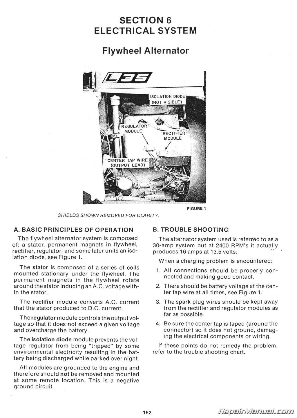
Basic principles of operation-flywheel
alternator
Motorola exterior alternator
Troubleshooting
FINAL DRIVE DISASSEMBLY AND ASSEMBLY
Additional information
Disassembly
Reassembly
FITTINGS
Adjustable
Bite-type flareless
Trouble shooting
FUEL TANK REMOVAL
HYDRAULIC CIRCUIT DIAGRAMS
L-35 – Cessna Transmissions
L-35 – Vickers Transmissions
L-775 – Cessna Transmissions
L-775 – Vickers Transmissions
L-778 Cessna Transmissions
L-779 Cessna Transmissions
HYDRAULIC SYSTEM PRESSURE CHECKS____
Checking the main system pressure
Hydraulic system
Main system relief valve
Transmission system
REBUILDING BUCKET AND BOOM CYLINDERS
Boom cylinders-double acting
Boom cylinders-single acting
Bucket tilt cylinder :
Identification
REPAIR OPERATIONS-AVERAGE TIME
SERVICING THE CONTROL VALVE
Lift check valves
Main system relief valve
Spools and O-rings
SPECIFICATIONS
L-35
L-775
L-778
L-779
START-UP PROCEDURE
Cessna-equipped loaders
Vickers-equipped loaders
TORQUE CHARTS
TROUBLE SHOOTING
Cessna
Hydraulic pumps
Vickers
INTRODUCTION
SAFETY
SERVICING CESSNA-EQUIPPED LOADERS
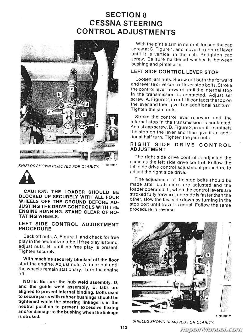
CESSNA STEERING CONTROL ADJUSTMENTS
High and low range control adjustment
Left side control adjustment procedure
Left side control lever stop
Right side drive control adjustment
CESSNA TANDEM GEAR PUMP REMOVAL
INSPECTION AND INSTALLATION
Inspecting and rebuilding the gear pump
Removing the gear pump
CESSNA TRANSMISSION REMOVAL
CESSNA TRANSMISSION OVERHAUL
Disassembly
Inspection and identification of parts
Reassembly
Winching valve
CESSNA TRANSMISSION OIL LEAKS
Gasket leaks
Pintle shaft leaks
Shuttle valve plug leak
GENERAL INFORMATION
HYDRAULIC RESERVOIR AND CHECK VALVE
ASSEMBLY
Cessna hydraulic systems
SHIMMING FOUR-WAY GEARBOX
Additional information
Drive shaft guard
Drive shaft installation
Rebuilding four-way gearbox in the loader
STEERING NEUTRALIZER REPAIR
SYSTEM CLEANING-PROCEDURE AFTER TRANSMISSION OVERHAUL
SERVICING VICKERS-EQUIPPED LOADERS
HYDRAULIC SCHEMATIC – L-35 AND L-775
PROPORTIONAL FLOW DIVIDER
Disassembly of the flow divider
Inspection and assembly
SHIMMING PROCEDURE FOR VICKERS
FOUR-WAY GEARBOX
Pre-load input shaft
Shimming transmissions to gearbox
STEERING CYLINDER REBUILDING
Disassembly
Inspection•
Reassembly
VICKERS HYDROSTATIC OPERATION
VICKERS STEERING CONTROL ADJUSTMENTS
Centering spring assembly
High and low range control adjustment
Left side drive control adjustment procedure
Left side drive control lever stop
Right side drive control adjustment
VICKERS TRANSMISSION REMOVAL
VICKERS TRANSMISSION DISASSEMBLY
Assembly
Disassembly of hydrostatic motor
Inspection and repair
Pump and motor
VICKERS TRANSMISSION PUMP AND MOTOR
SHIMMING
Assembly
Motor
Shimming procedure
Pump
VICKERS VANE PUMP INSPECTION, REMOVAL
AND INSTALLATION
Determining extent of pump problem
Pump installation
Rebuilding the vane pump
Removing vane pump


