Description
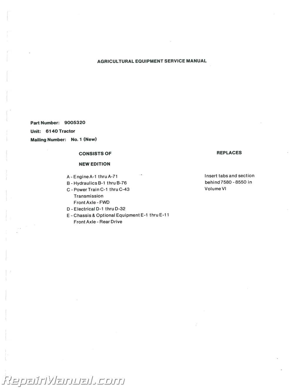
This 240 page, printed Allis Chalmers 6140 Tractor Service Manual is a reproduction of the original, out of print manual. This tractor service provides detailed service information, step-by-step repair instruction and maintenance specifications for Allis Chalmers 6140 tractors.
Table of Contents
ENGINE SECTION
Description
Power Curve
Engine Features
Specifications
Fits and Tolerances
Engine Torque Specifications
Engine Cooling System
Radiator
Fan and Fan Belt
Thermostat
Water Pump
Cylinder Head and Valves
Valve Valve Guide and Valve Seat Ring
Timing Gear Cover
Crankshaft Pulley
Diesel Gear Train
Injection Pump Drive Gear
Idler Gear and Shaft
Front Plate
Flywheel and Ring Gear
Rear Plate and Crankshaft Rear Oil Seal
Camshaft Gear Keyway and Timing Mark Location
Camshaft and Camshaft Gear
Valve Lifters
Piston and Piston Rings
Connecting Rods and Connecting Rod Bearings
Crankshaft and Main Bearings
Main Bearing Caps
Piston, Connecting Rod and Connecting Rod Bearing Installation
Main Bearing Bearing Cap and Crankshaft Installation
Cylinder Block
Engine Lubricating System
Crankcase
Engine Oil Pump
Oil Control Housing and Oil Cleaner
Checking Compression Pressure
DPA Mechanically Governed Pumps
Introduction
Pump Removal & Installation
Timing Pump to Engine
Injection Nozzle and Nozzle Holder
Injection Nozzle Check
Engine Tools
POWER STEERING SECTION
Gearbox Operation
Relief Valve Pressure Test
Flow Rating Power Steering Pump
Power Steering Gearbox Removal
Gearbox Disassembly
Gearbox Reassembly
Cross Shaft Adjustment
Gear Pump Disassembly & Reassembly
Gearbox Troubleshooting
Gearbox Specifications
HYDRAULICS SECTION
Operation
Hydraulic Cylinder Housing Removal
Hydraulic Cylinder Housing Disassembly
Flow Control Valve & Housing Cover Removal
And Disassembly and Assembly
Piston Removal
Lifter Arm & Hydraulic Arm Removal
Control Valve Disassembly
Control Valve Reassembly
Control Valve Specifications
Cover Assembly Disassembly
Relief Setting
Top Link Bracket Disassembly & Assembly
Hydraulic Cylinder Housing Reassembly
Adjustments
Draft Control Sensing Adjustment
Disassembly/inspection and Reassembly of Gear Pump
Torque Specification/pump
Hydraulic Cylinder Troubleshooting
Remote Valve Stack
Disassembly Relief Valve
Remote Valve Operation
Detent Operation
Remove and Disassembly Remote Valve
Assembly Remote Valve
Coupler Repair and Operation
Remote Valve Installation
Testing & Adjusting Remote Valve Relief
Testing Hydraulic Pump
Test Equipment & Fitting
Metric Information
TRANSMISSION SECTION
Specifications
Separating Power Train
Oil Draining
Removing Tractor Hardware
Separating the Housing Unit
CLUTCH
Disassembly of Clutch Assembly
Checking
Assembly of Clutch
Adjustment
Disassembly of Clutch Control
Checking
TRANSMISSION
Disassembly of Shift Cover Assembly
Disassembly of Fork and Rod
Disassembly of Control Cover Assembly
Checking
Assembly of Cover
Disassembly of Main Drive Shaft Assembly
Adjustment of Axial Direction Clearance
Assembly of Main Drive Shaft
Disassembly of Countershaft Assembly
Adjustment of Countershaft Assembly
Assembly of Countershaft
Disassembly of Main Shaft Assembly
Adjustment of Axial Direction Clearance
Assembly of Main Shaft
Disassembly of Reverse Idler Shaft Assembly
Adjustment of Axial Direction Clearance
Assembly of Reverse Idler Shaft
Drive Pinion Shaft Disassembly
Tapered Bearing Disassembly for Pre-load Adjustment
Pre-load Adjustment (Drive Pinion Shaft)
Adjustment of Axial Direction Clearance
Drive Pinion Shaft Assembly
Disassembly of Front Drive Shaft Assembly
Adjustment of Axial Direction Clearance
REAR HOUSING SECTION
Differential Lock Control Disassembly
Differential Lock Control Assembly
Disassembly of Axle Assembly(RH:LH)
Pre-load Adjustment (Axle)
Assembly of Axle
Disassemblyof Differential Assembly
Assembly of Differential
Differential Assembly Adjustment
Check Tooth Contact
Disassemblyof PTO Shaft Assembly
Adjustment of Axial DirectionClearance
Assembly of PTO Shaft
BRAKE ASSEMBLY
Disassembly
Checking
Assembly
Adjustment
POWER TRAIN CROSS SECTIONS
Rear Axle 66663
Two-Wheel Drive 66664
Front Wheel Drive Option 66665
FRONT AXLE – FWD SECTION
General
Disassembly of Axle Assembly
Hub Disassembly
Disassembly of Differential Carrier
Disassembly of Differential Assembly
Disassembly of Pinion Case
Pinion Adjustment and Assembly
Differential Assembly
Differential Carrier and Carrier Brackets
Front Axle Seals and Bearings
Front Gear Case and Lower Arm
Case Support and Lift Bolt
ELECTRICAL SECTION – WIRING DIAGRAM
STARTER MOTOR – 12V Reduction Type Starter
Features & Construction
Performance Specifications –
Disassembly Procedure
Inspection and Service
Assembly
Troubleshooting Chart
ALTERNATOR – 12V 35A Alternator w/IC Regulator
Features and Construction——
Handling Precautions
Troubleshooting Chart
Disassembly
Inspection & Service
Reassembly
Bench Test
FRONT AXLE SECTION (Chassis & Optional Equipment) (2 Wheel Drive)
Front Axle and Steering Linkage
Front Axle Tread Adjustment
Front Axle Disassembly
Disassembly & Reassembly or Counter Arm & Drag Link
Front Wheel Hub Disassembly & Reassembly
Front Axle Alignment
New Parts Dimensions and Wear Limits
Standard Tightening Torques


