Description
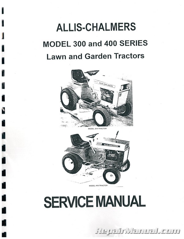
This 127 page, Allis Chalmers Model 300 and 400 SERIES Lawn and Garden Tractor Service Manual provides detailed service information, step-by-step repair instruction and maintenance specifications for Allis Chalmers Model 300 and 400 Series tractors, specifically:
300 310 310D 312 312D/H 314 314D/H
400 410 414S 416H 416B
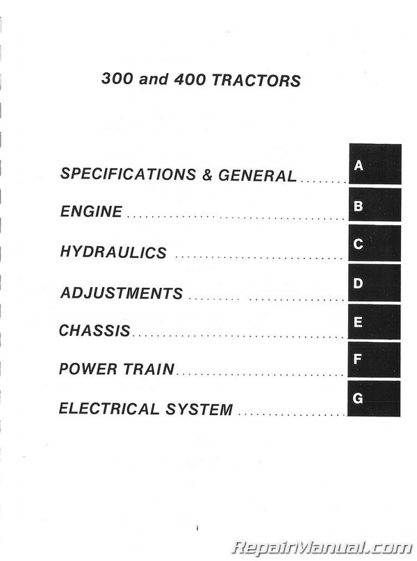
Table of Contents
SPECIFICATIONS & GENERAL INFORMATION
300 Series Specifications
400 Series Specifications
Service Tips
ENGINE
General Engine Specifications
Service Adjustment Points
Safety Precautions
Pre Start Check List
Starting Procedure
Stopping Procedure
Service Schedule
Lubrication
Air Cleaners
Cool and External Surfaces
Fuel Fuel Systems
Carburetor
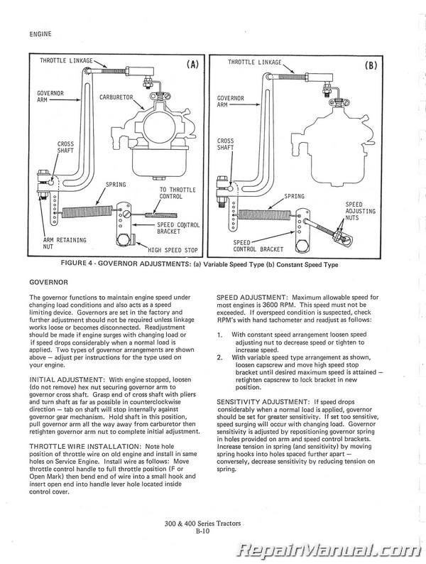
Governor
Ignition System Service
Electrical Start Models
Storage Instructions
Trouble Shooting
HYDRAULICS
Introduction of Hydrostat
Purpose of Manual
Description
General Information
General Overhaul Procedures
Disassembly
Tools
Disassembly of Motor
Disassembly of Pump
Disassembly of Valve Plate
Disassembly of Transfer Block
Inspection and Repair
Assembly
Piston Pump
Replenishing Pump and Valving
Start-Up After Repair
General Maintenance
Lubrication
Adjustments
Adding Fluid to System
Oil Filter
Servicing
Transmission Servicing Guide
System Servicing Guide
Hydrostatic Cooling System
Hydrostatic Oil and Filter
300 SERIES TRACTORS ADJUSTMENTS
Clutch
Brake
Hydrostatic Control
Variable Speed Control
Belt Slippage Adjustments
Variable Speed Adjustment Check
Manual Power Take-Off
Electric Power Take-Off
Seat Adjustment
400 SERIES TRACTORS ADJUSTMENTS
Seat Adjustment
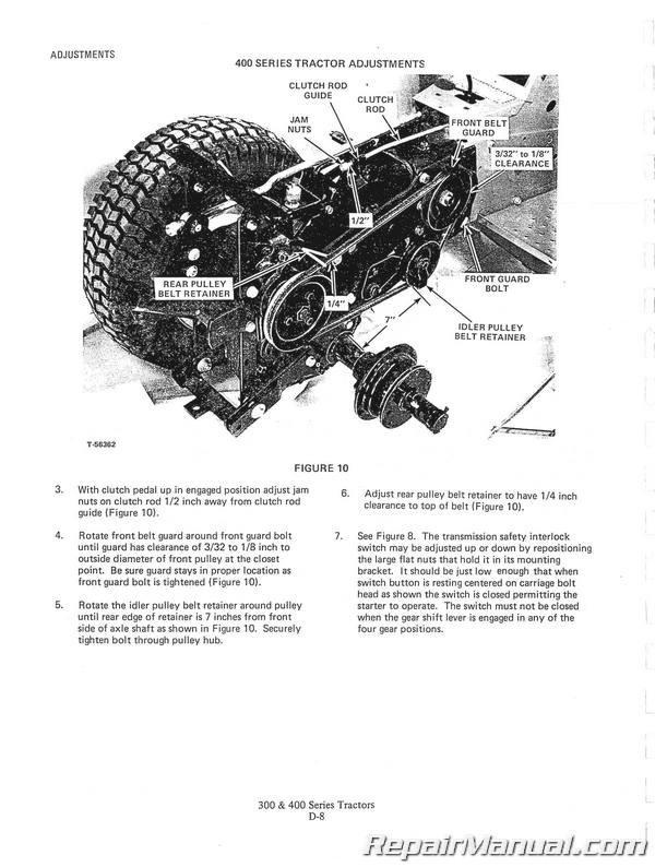
Front Power Take-Off Idler Adjustment
Tractors with 3-Speed Transmission
Tractors with Shuttle Clutch
Tractors with Hydrostatic Transmission
CHASSIS
Steering Gear Box (300 & 400 Seriesl
Steering Linkage (300 & 400 Series)
Front Axle Asy (300 Series) ,
Front Axle Asy (400 Scries)
Front Wheel Bearings (300 & 400 Series)
Clutch and Brake System – Variable Speed
Transmission (300 Series)
Shuttle Clutch Control (400 Series)
Clutch and Brake System – Shuttle Clutch
(400 Series) & Direct Drive (300 & 400 Series)
Hydrostatic Controls (300 & 400 Series)
Clutch and Brake System – Hydraulic
Transmission (300 Series)
Clutch and Brake System – Hydrostatic
Transmission (400 Series)
Drive Shaft (300 & 400 Series)
Electric Lift (300 & 400 Series)
Specifications
Motor Inspection
Motor Assembly
Ball Bearing Screw & Brake Assembly
Outer Tube
Gear Case
Installation of Clutch and Shaft Assembly In Gear Case
Overload Clutch and Gear Assembly Inspection
POWER TRAIN
Transmission
Transmission Removal
Transmission Disassembly
Bearing Installation in Case
Bearing Installation in Cover
Gear and Shaft Installation in Case
Brake Drum Shaft Assembly
3rd Intermediate Shaft Assembly
2nd Intermediate Shaft Assembly
Four Speed Shuttle Clutch Transmission
Three Speed Transmission
Shifter Forks and Shaft
Axle Tube and Gears
Differential and Axle Assembly Removal
Differential Assembly Installation
Bevel Gear Box
Bevel Gear Box Removal
Bevel Gear Box Disassembly
Bevel Gear Box Assembly
Seal Installation
Bevel Gear Box Installation
Hydrostatic Transmission
Remove and Reinstall
Overhaul
Variable Speed Pulley
Disassembly
Turnbuckle Removal
Clutch – Brake & Belt Adjustment
Belt Slippage
Lubrication
Shuttle Clutch
Introduction
Forward
Feather Forward
Neutral
Reverse
Feather Reverse
Shuttle Clutch Removal
Disassembly and Assembly of Planetary Unit
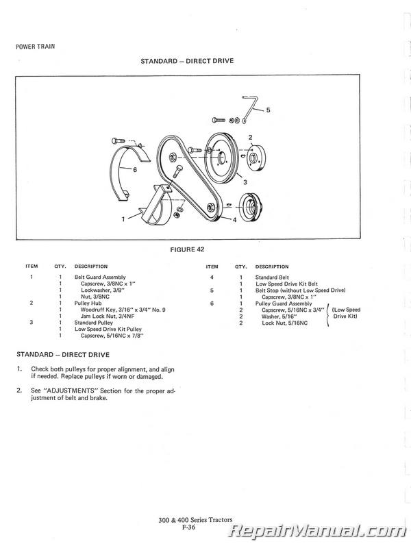
Standard-Direct Drive
ELECTRICAL SYSTEM
Description
Battery Circuit
Battery
Battery Care
Winter Care
Regulator – Rectifier
Wiring Conduit
Charging Conduit
Starting Circuit
Common Terms
Voltage
Amperes
Resistance
Multi-Meter
Circuit — Continuity
Switches
Starting Circuit
Direct Current
Wiring Diagram (Magneto Ignition)
Wiring Diagram (Breaker Point Ignition)

